Quick Start Guide
How to Unpack (Standing Position)
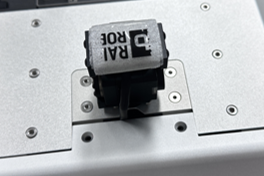
Step 1: Open the Torso Cover
Open the front cover on the torso by unscrewing the two bolts near the head area.
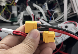
Step 2: Connect the Cables
Connect the two connectors as shown below.
⚠️ Note: Sparks may occur during the connection.
Step 3: Access the Web UI
Connect via HOTSPOT at: 192.168.12.1:5173
Step 4: Initialize the Robot
Power on the system and follow these steps:
- Power On → Servo On → Control Enable → Move to Zero Position
Web UI Overview
The Web UI allows users to monitor the robot's status and access different control settings. Below is an explanation of the key elements in the interface.
⚠️ This is for basic use only. This robot is a research platform intended for user-driven handling through custom code.
Key Features:
Tabs:
- Access different sections such as:
- Dashboard: Displays overall system status and key metrics.
- Settings: Modify system configurations.
- Controls: Control and monitor the robot's movements.
- Access different sections such as:
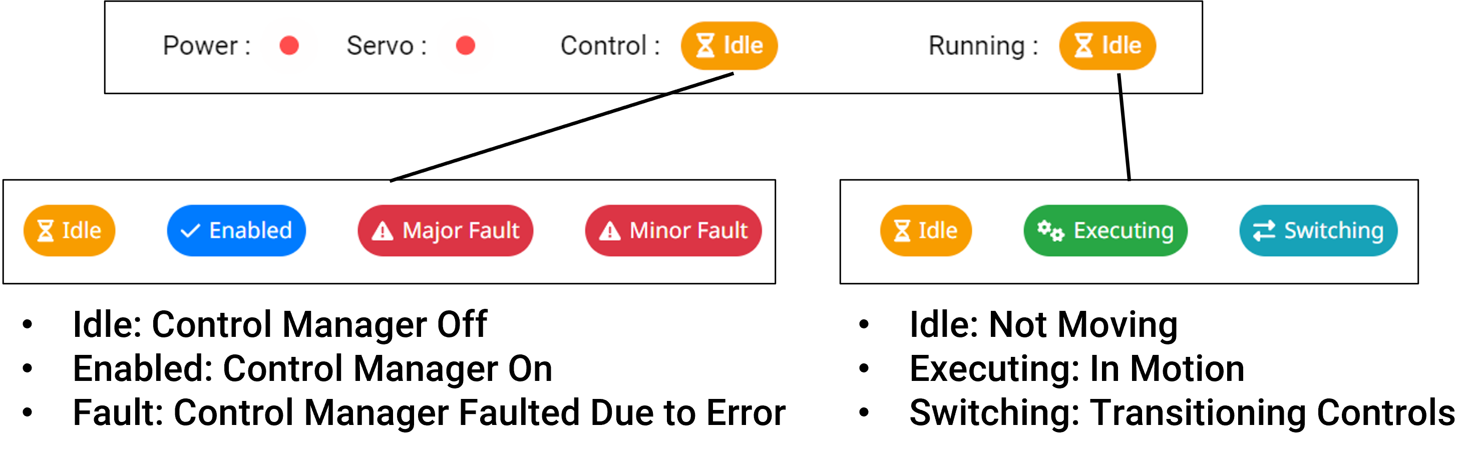
Status Lamp/Badge:
- Indicates the current status of the robot (e.g., Power, Servo, Control, Running).
Metrics:
- Uptime: Displays the duration that the RPC program has been running.
- CPU & Memory Usage: Shows the CPU and memory usage of the RPC program.
- Current & Voltage:
- Current: Displays the current consumed during robot motion.
- Voltage: Shows the remaining battery voltage.
⚠️ Note: Web access may take up to 2 minutes to become available after powering on.
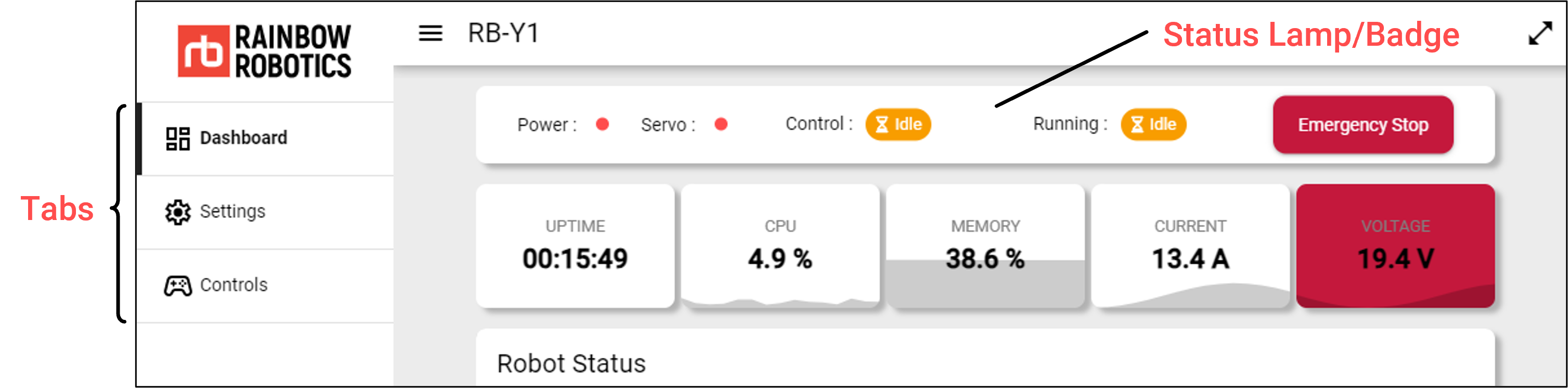
Status Indicators
The status of the robot is visible on any tab in the Web UI. The indicators show the current state of the system components, including power, servo, control, and running status.
Power:
- 🔵 (On) 🔴 (Off)
Servo:
- 🔵 (On) 🔴 (Off)
Control & Running:
- Refer to the image below.
Dashboard
System Monitor
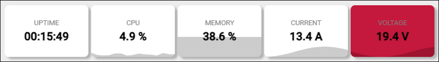
- Uptime: Time since the RPC program started
- CPU: CPU usage of the RPC program
- Memory: Memory usage of the RPC program
- Current: Battery current usage
- Voltage: Remaining battery voltage
Robot Status
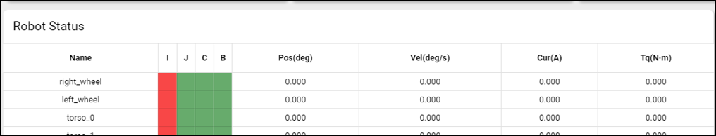
- Name: Joint/Actuator name
- I, J, C, B: Error state indicators (error codes)
- I (Init): Actuator is not in the ready state (Servo On failed)
- J (Jam): Error due to mechanical jamming; occurs when the encoder value does not change over a set period of time, indicating the joint is stuck.
- C (Current): Error occurs when the current exceeds a certain threshold, even if the encoder value changes slightly.
- B (Big): Error occurs when the difference between the reference value and the current value is too large.
- Pos (deg): Current joint angle (encoder value)
- Vel (deg/s): Current joint speed
- Cur (A): Input current to the motor
- Torque (Nm): Estimated torque at the motor output, derived from the input current
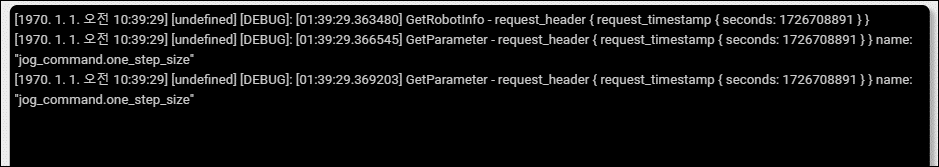
Logs
Settings
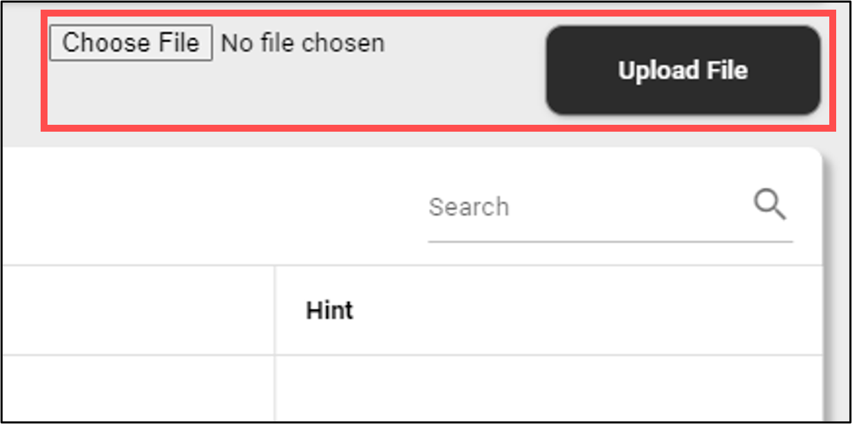
Update
- Use the "Select File" button to choose the RPC update file.
- Use the "Upload File" button to start uploading the file to the RPC.
- This process may take some time (under 10 minutes).
- Once completed, the RPC will automatically reboot.
Parameter Configuration
- Read and write robot parameter settings.
- ⚠️ Currently not implemented.
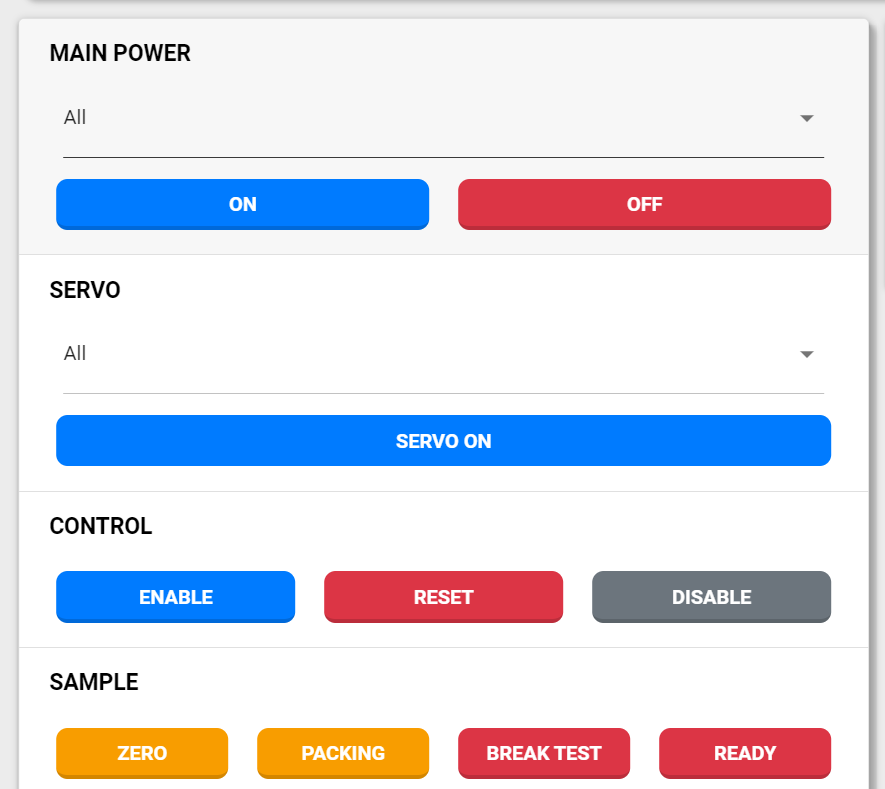
Controls
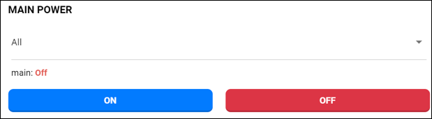
Main Power
- Real Robot Case: 48V, 24V, 12V, 5V (Robot must have 48V on to operate)
- Simulation Case: main
Servo
- Actuator list(Total: 24)
- right_wheel, left_wheel (Mobility)
- torso_0 to torso_5 (Body)
- right_arm_0 to right_arm_6 (Body)
- left_arm_0 to left_arm_6 (Body)
- head_0, head_1 (Head)

Control
- Enable: Activate Control Manager
- Reset: Reset Control Manager Fault
- Disable: Deactivate Control Manager

Sample
This function moves the robot to a predefined position. The movement time is affected by the minimum time setting, so caution is advised.
- Zero: All joints at zero position
- Packing: Packaging Position
- Brake Test: Testing Position1 (Torso bent, elbows outward, grippers near torso)
- Ready: Testing Position2 (Torso bent, elbows folded)

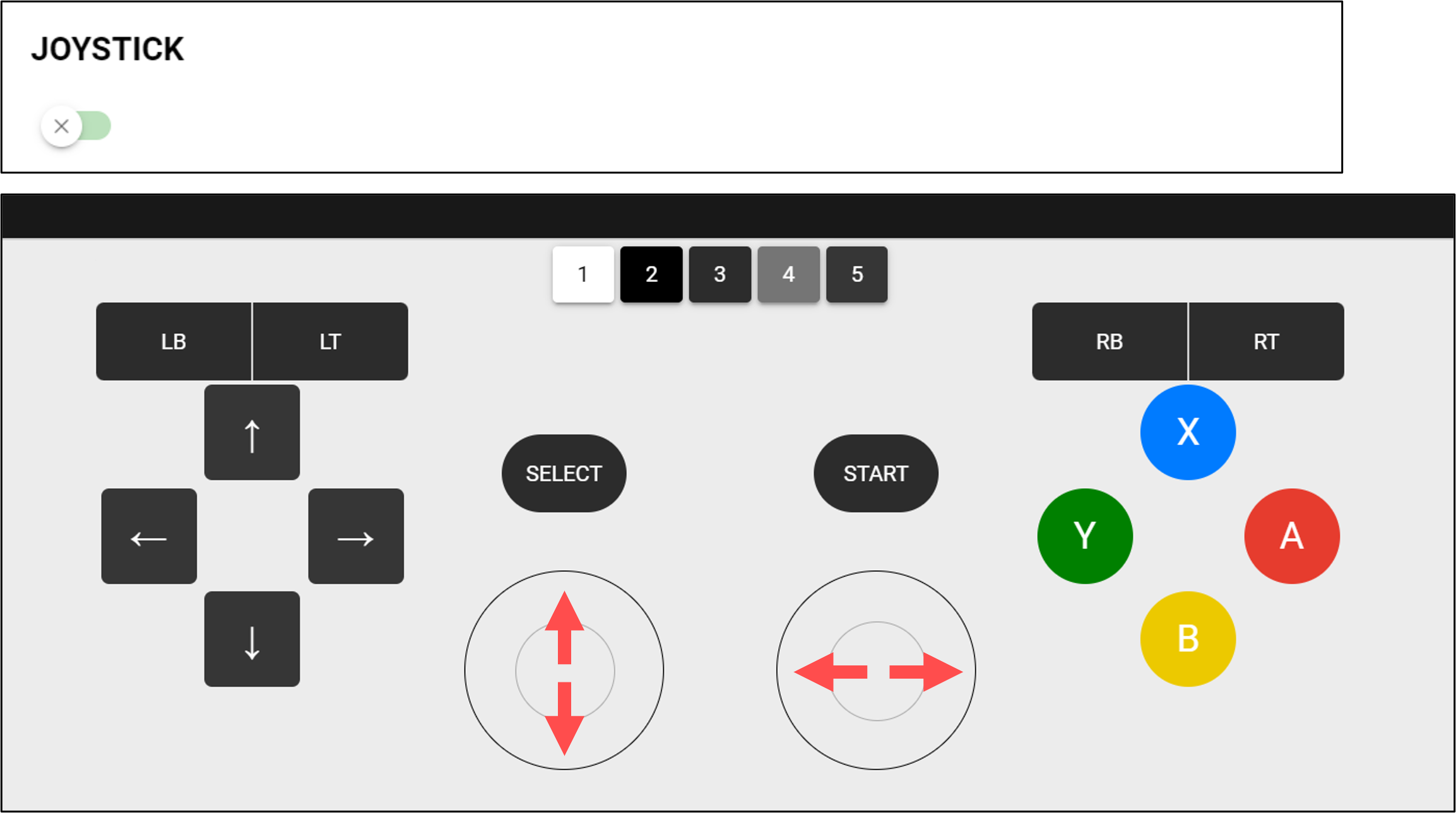
Joystick
- Used for mobile control, driven by linear velocity and angular velocity
- Up: Increase x-direction velocity
- Down: Decrease x-direction velocity
- Left: Counterclockwise angular velocity
- Right: Clockwise angular velocity
💡 Other buttons are not yet mapped.
Break
- Used for mobile control, driven by linear velocity and angular velocity
- The brake is automatically released when Servo On is activated.
- Use this function only for manual testing if the brake does not release correctly.
- ⚠️ Never use “All.” Use only the following list.
- torso_0 to torso_5
- right_arm_0 to right_arm_6
- left_arm_0 to left_arm_6

Tool Flange
- Power output
- 24V, 12V
- Requires main power (48V) to be on for activation
- Only "Left" and "Right" are available.

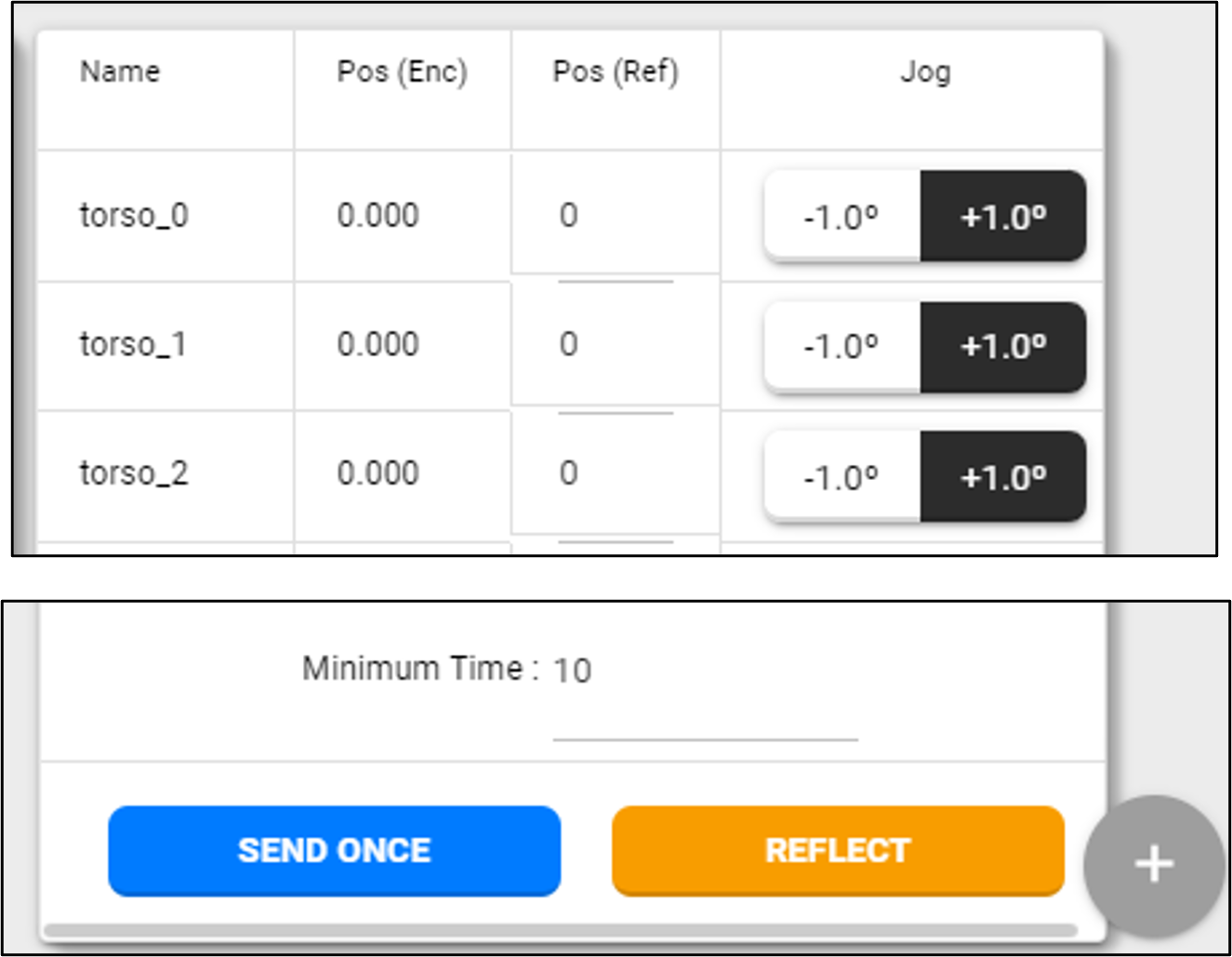
Jog & Target Position
- Jog
- Moves based on +/- input.
- Jog amount varies with robot parameter settings.
- Target Position
- Enter desired value in Pos(ref) (in degrees).
- Press "Send Once" to move.
- Time to reach the target varies with minimum time setting.
- "Reflect" button sets the current encoder value as the ref value.
⚠️ Pay attention to the joint movement direction (+/-) to ensure correct operation.
How to Pack (Packing Position)
This position is not commonly used during regular operation. However, it can be used when preparing to send the robot to another location, along with the packaging box in which it was delivered.
⚠️ Important: Extreme caution is required when transporting the robot. If you are unsure or need assistance, it is highly recommended to contact support via email at rby.support@rainbow-robotics.com.
Step 1: Access the Web UI
Connect via HOTSPOT at: 192.168.12.1:5173
Step 2: Insert the Included Sponge
Insert the included sponge and follow these steps:
- Power On → Servo On → Control Enable → Move to Packing Position
Step 3: Open the Torso Cover
Open the front cover on the torso by unscrewing the two bolts near the head area.
Step 4: Disconnect the Cables
Disconnect the two connectors as shown below.