Eletrical Part
Power System
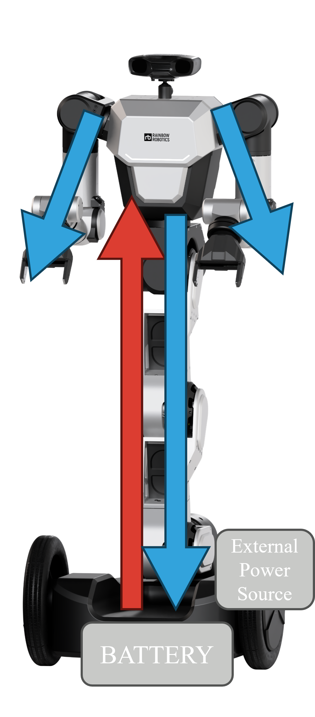
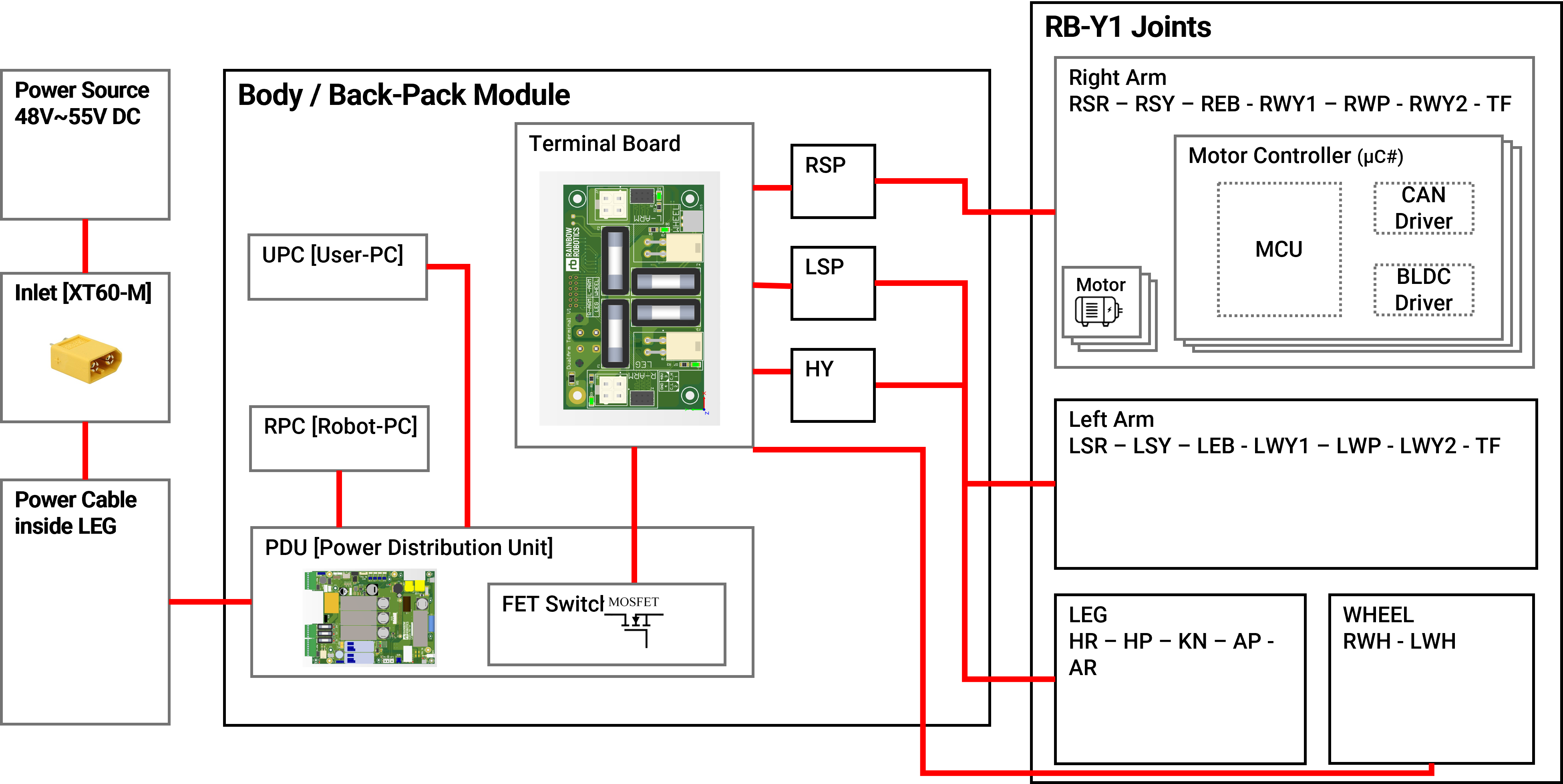
Input Source
- The system operates using either a battery or an external power source (SMPS).
- The SMPS (Switched-Mode Power Supply) requires a back-EMF protection device to safeguard against voltage spikes.
Power Distribution
- Power is routed through cables inside the robot's legs to minimize visible wiring.
- It is then distributed to different parts of the robot's body.
- The design effectively hides and protects cables, enhancing durability.
Shutdown Methods
Complete Removal
- Disconnect the input power source by accessing the front panel.
- This method is ideal for packaging or long-term storage.
Emergency Stop Button
- A software-based switch designed to cut off power to each module.
- It can be user-defined for safety, especially during operation.
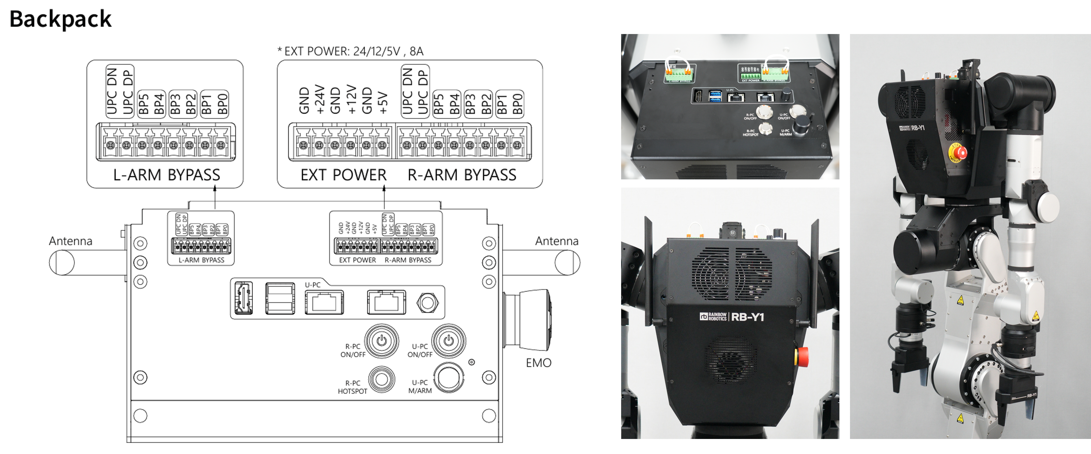
Backpack
The Backpack section explains the internal structure and layout of the robot's control unit. It facilitates external connections, allowing power to flow through bypass ports from the Tool Flange to the control unit. Supported power options include 24V, 12V, and 5V, with a current capacity of 8A. Additionally, the U-PC (User PC) has accessible ports: 2 USB, 2 Ethernet, and 1 HDMI. Antennas, power buttons, and the emergency stop (EMO) switch are all positioned for easy access on the backpack. This unit manages power, controls the robot, and allows external devices to connect seamlessly.
External Power Specifications
| Voltage | Current Capacity |
|---|---|
| 24V | 8A |
| 12V | 8A |
| 5V | 8A |
The robot's body is designed to distribute power and communication to each critical module for smooth operation.
Key Components Installed in the Body:
- R-PC (Robot PC): UP Xtreme i12
- U-PC (User PC): Jetson AGX Orin
- Emergency Stop Switch: Instantly cuts robot power.
- PDU (Power Distribution Unit): Manages power distribution.
- OLED: Displays robot status.
- LED Strip: Visual robot status indicator.
- Pan-Tilt Mount: For mounting vision devices.
U-PC and R-PC
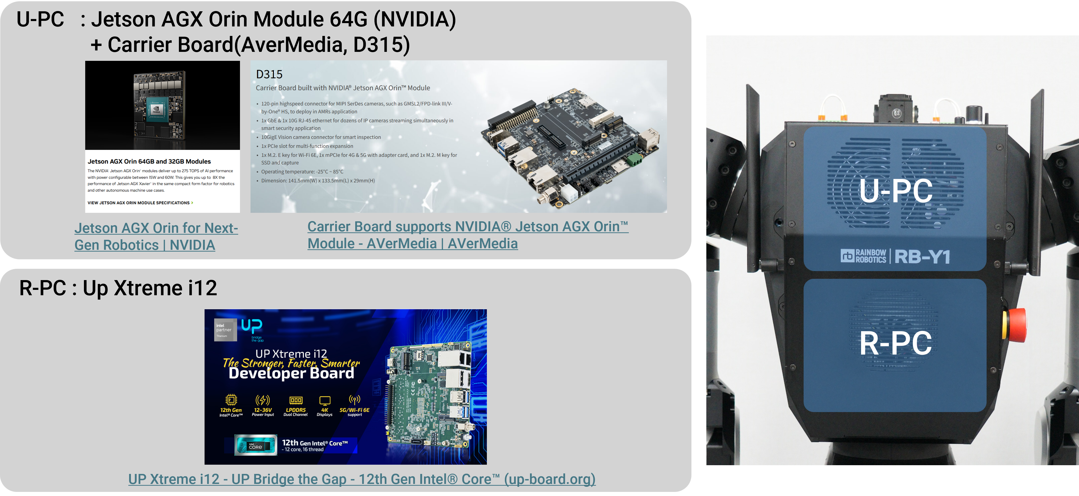
- The U-PC is powered by a Jetson AGX Orin Module 64G paired with a Carrier Board (AverMedia, D315). This setup offers high-performance processing for complex robotics operations.
- The R-PC consists of an Up Xtreme i12 equipped with a 12th Gen Intel® Core™ processor. This serves as the processing hub for robotic actions.
R-PC [Robot PC]
The R-PC, specifically the UP Xtreme i12, receives its input power via a DC-DC converter embedded in the PDU. The power switch for the R-PC is easily accessible on the robot's top section. Additionally, the R-PC is equipped with a 4-channel M.2 CAN module, serving as the primary interface for CAN communication with each joint.
U-PC [User PC]
The U-PC is the Jetson AGX Orin, which can be swapped for another PC if necessary. Its input power is also supplied by a DC-DC converter housed within the PDU. The U-PC switch is located at the top of the body. The U-PC controls the robot's gripper, and users must connect the correct communication module to operate different types of grippers effectively.
PDU (Power Distribution Unit)
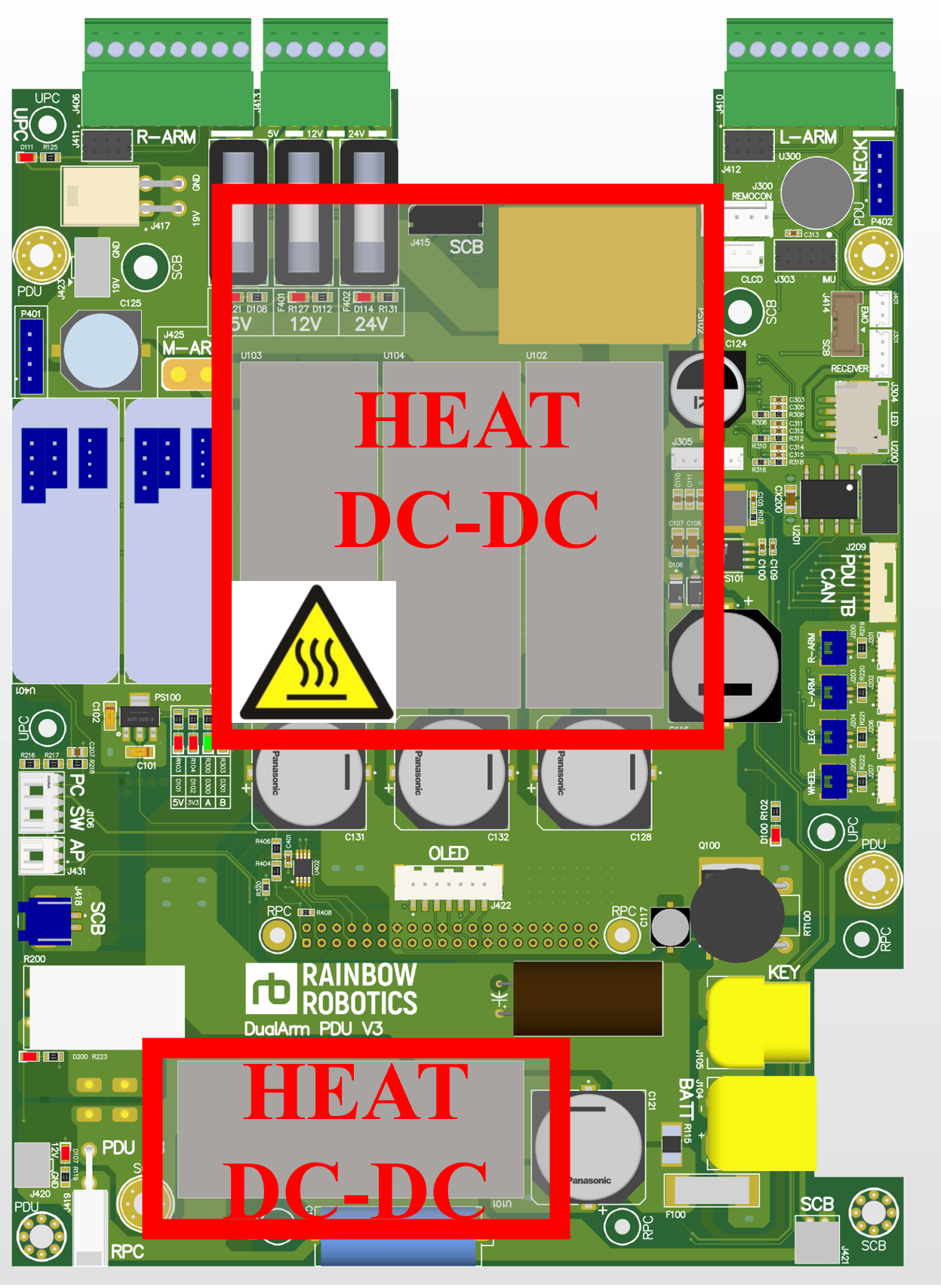
The PDU has around 20 connectors, and incorrect wiring can lead to operational issues. Special caution is necessary when handling the PDU, particularly around its DC-DC converters, as they can become very hot during operation.
⚠️ Important Note:
Be cautious not to touch the DC-DC converters while the power is on, as they can become hot.
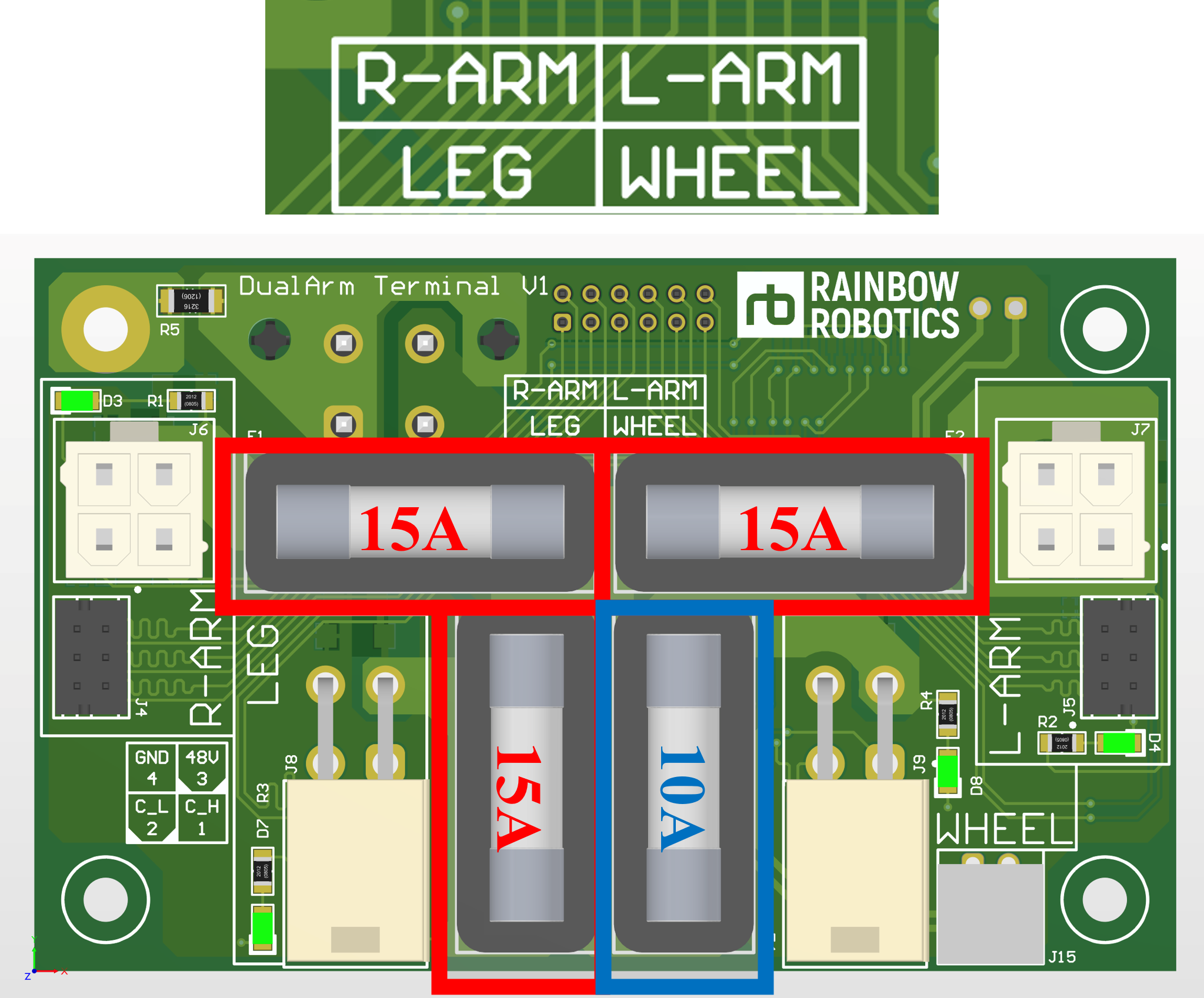
Terminal Board and Fuse Information
The Terminal Board inside the robot contains four fuses:
- Fuse types: 5x20mm
- Ratings: 15A and 10A fuses
Correctly configuring the fuses ensures the smooth functioning of connected modules.
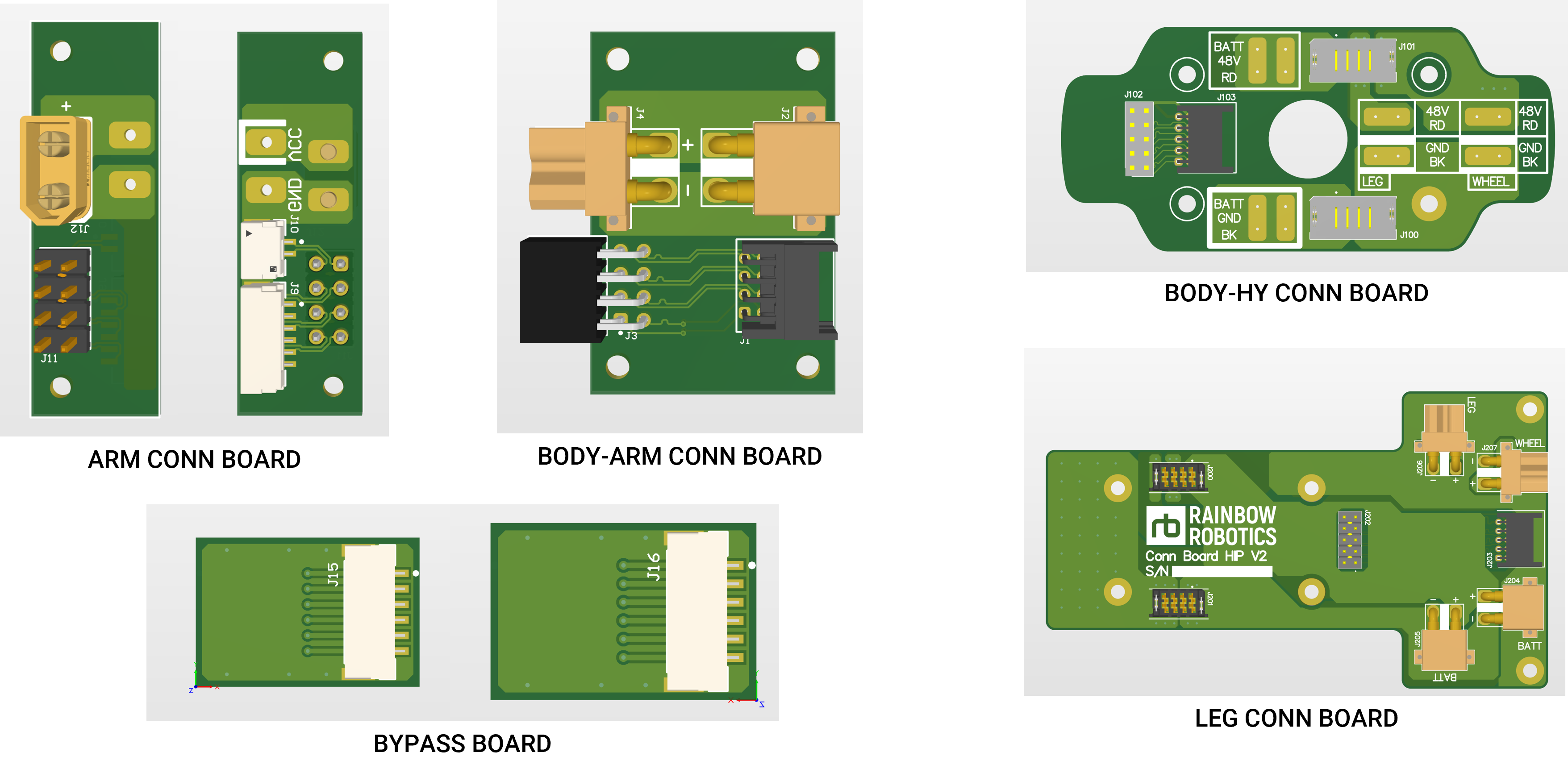
Cable Connection Board
This board manages the power and signal connections between the robot's modules.
Tool Flange Connection
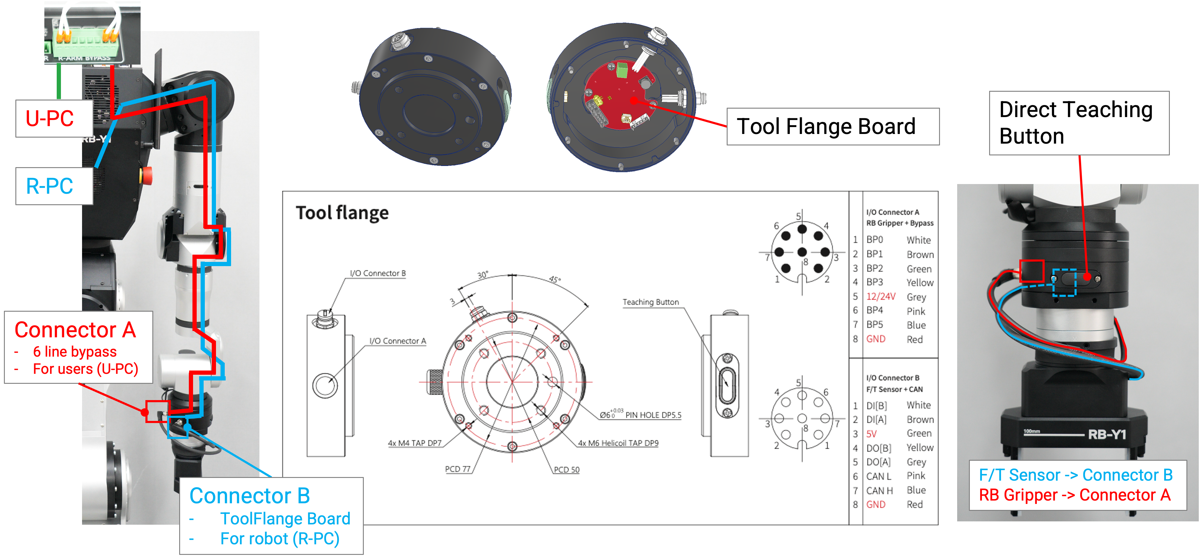
The robot's tool flange includes Connector A for users, which provides a 6-line bypass connected to the U-PC. Connector B is linked to the tool flange board and routed to the R-PC for robot control. The tool flange also features an I/O interface, supporting direct connections to the robot’s force/torque (F/T) sensor or gripper. Additionally, the Direct Teaching Button allows users to manually guide the robot’s movements.
Communication System Overview [CAN]
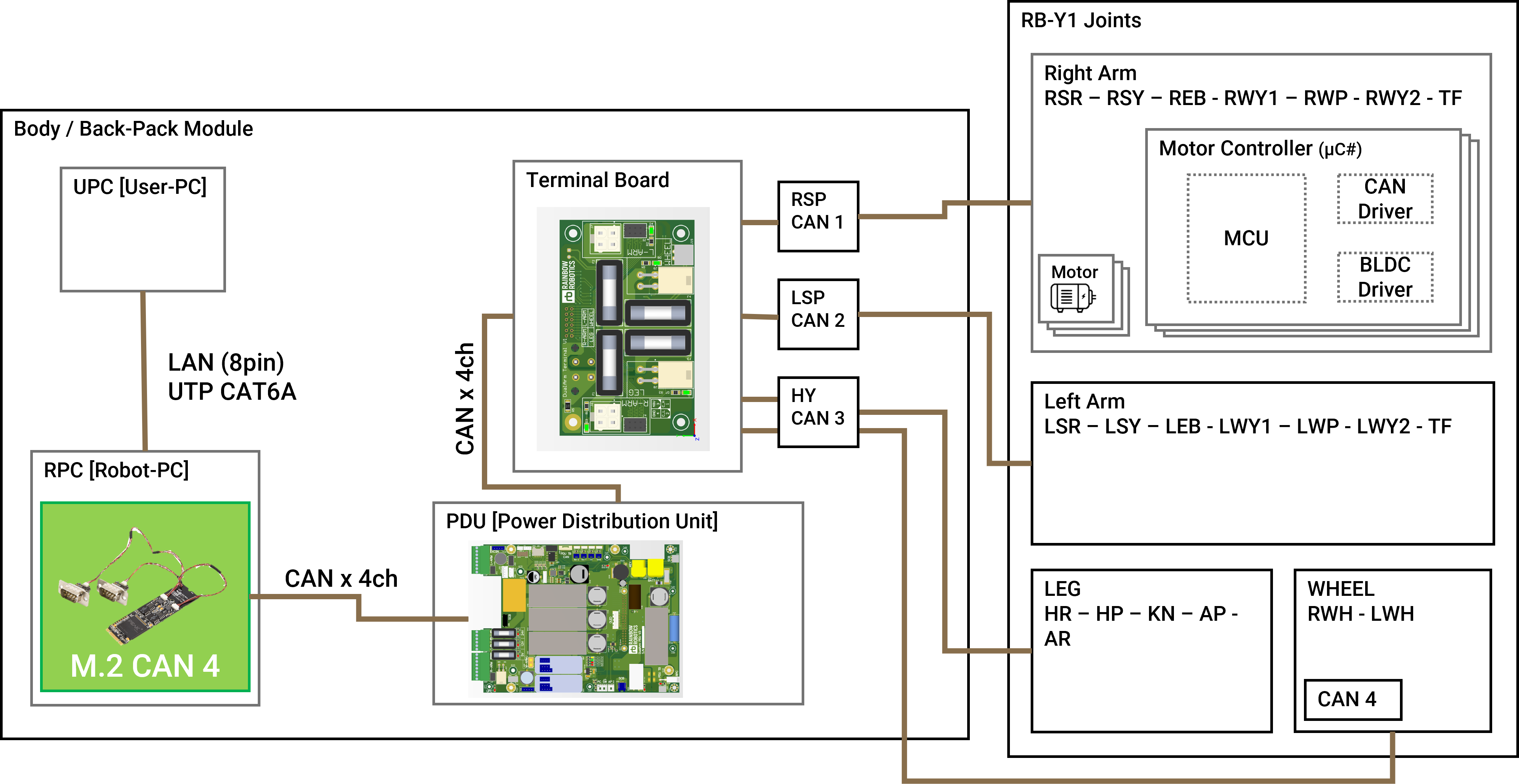
⚠️ Note: These CAN channels are not accessible to users. They are exclusively managed by the R-PC (Robot-PC).
CAN Channels:
- Generated by the R-PC (Robot-PC) inside the body.
- A total of 4 channels are used:
- CAN0: Right Arm (R-ARM)
- CAN1: Left Arm (L-ARM)
- CAN2: Leg (LEG)
- CAN3: Wheel (WHEEL)
Data Transmission:
- The motor driver status and joint encoder values are transmitted via CAN.
Command Flow:
- The user sends commands to the R-PC via U-PC over an Ethernet link.
- The R-PC processes these commands and communicates with the joints and CAN system through its embedded program.
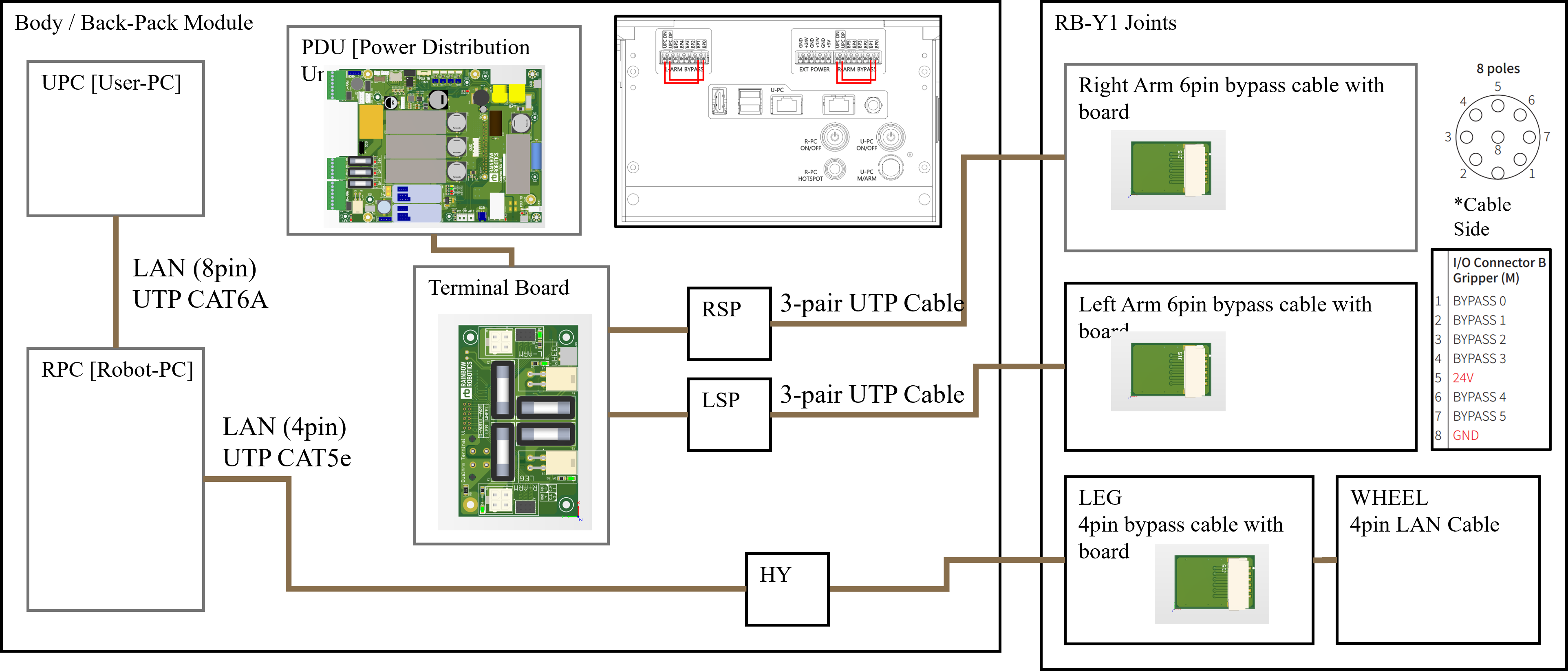
Communication System Overview [LAN & BYPASS]
Access through U-PC:
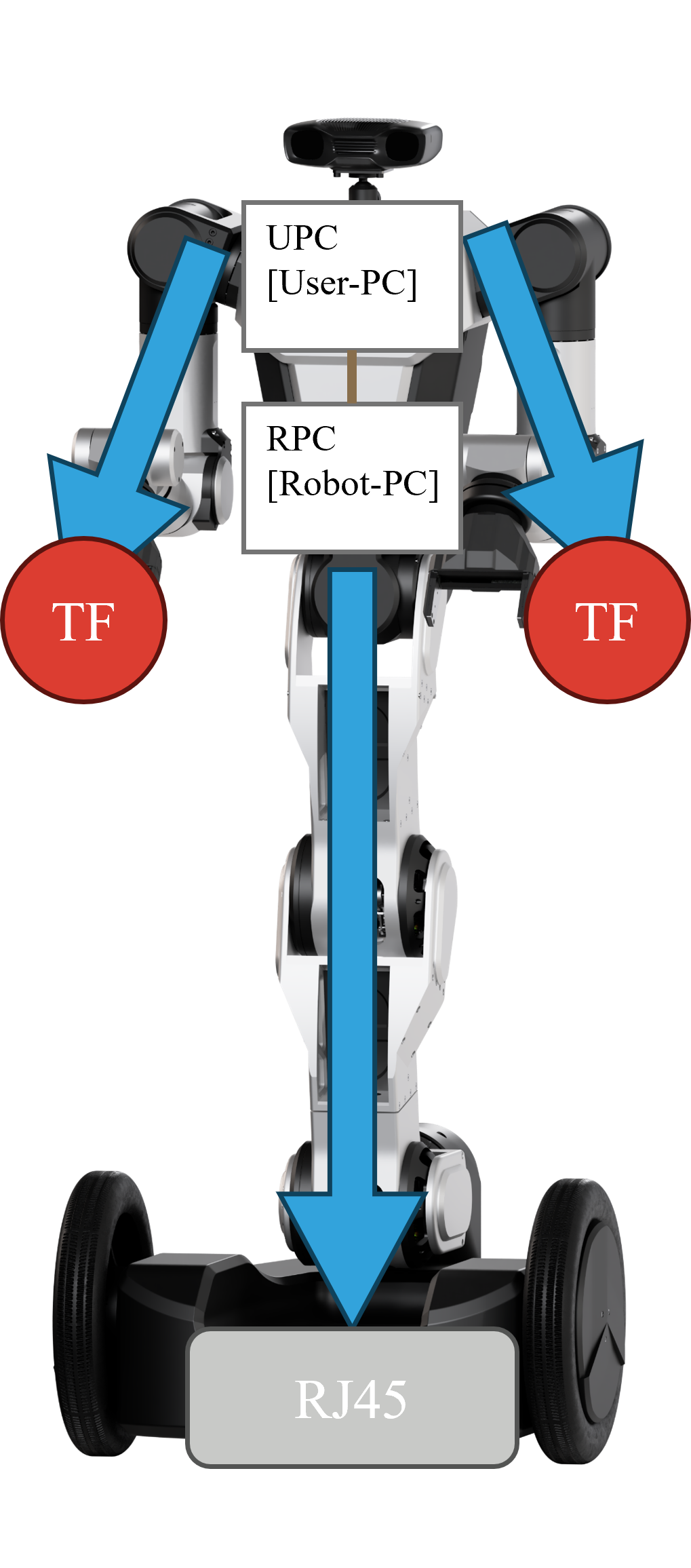
- The user communicates with the R-PC via LAN.
- Commands are sent from the U-PC to the R-PC to control the RB-Y1.
R-PC to Mobile Robot:
- The R-PC is connected to the mobile robot via LAN.
- It receives sensor data such as LiDAR for tasks like collision avoidance.
Bypass Connection:
- A direct hardware link exists between the body and the tool flange (TF).
- This connection allows communication for devices like grippers.
Peripheral Devices:
- The user can connect additional devices, such as USB-to-serial converters, for extended functionality.
