Skip to content

External Port Information

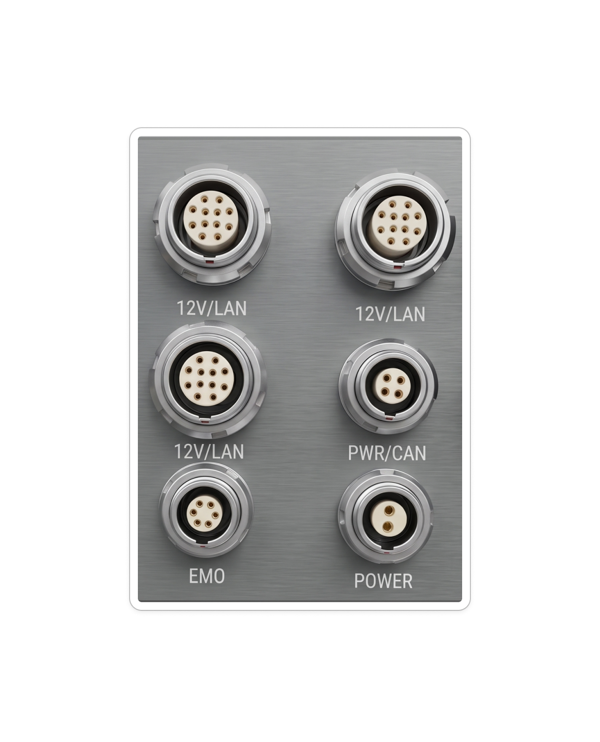
Overall External Port Panel

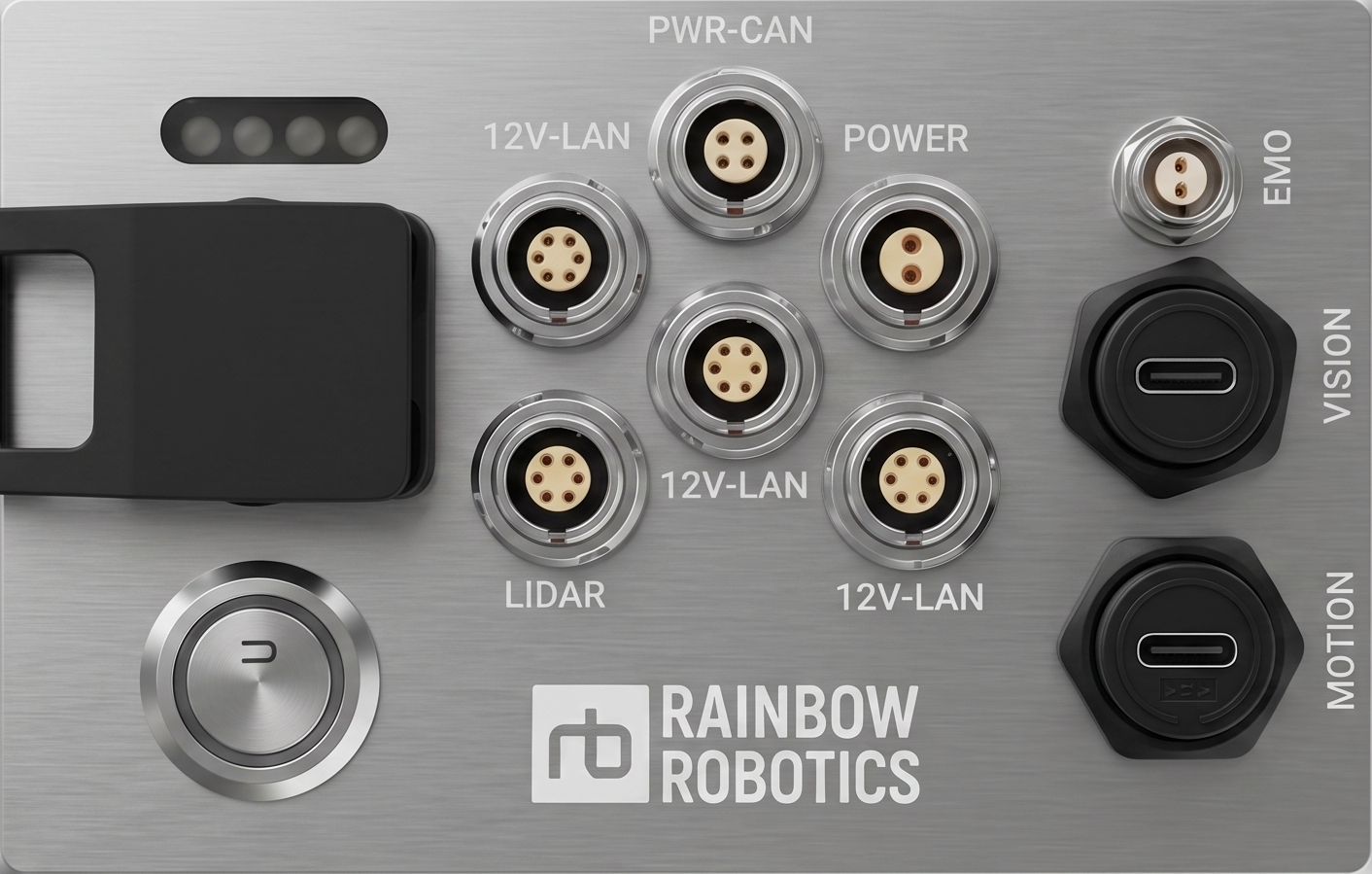
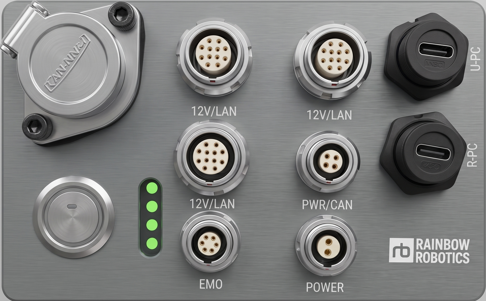
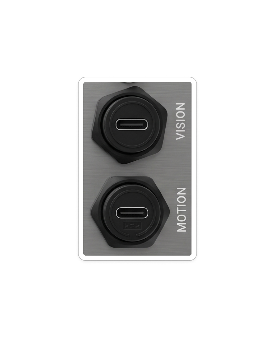
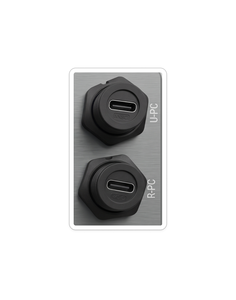
There are two panel layouts — version 1 and version 2 — and which one your robot has depends on the robot. The quickest way to tell them apart is the pair of USB-C ports on the right edge: version 1 labels them VISION / MOTION, version 2 labels them U-PC / R-PC. They are the same two ports — version 2 names the PC each one reaches instead of its role.

NOTE

The panel layout can differ between versions. Please contact us if you are unsure which one your robot has.

External port panel, version 1
Version 1
External port panel, version 2
Version 2

Ports by version

PortVersion 1Version 2
PowerPOWERPOWER
Power · CANPWR-CANPWR/CAN
Power · LAN12V-LAN ×312V/LAN ×3
LiDARLiDARNo dedicated port — use 12V/LAN
Emergency stopEMOEMO
USB-C (direct to PC)VISION, MOTIONU-PC, R-PC

Charging & Power Switch

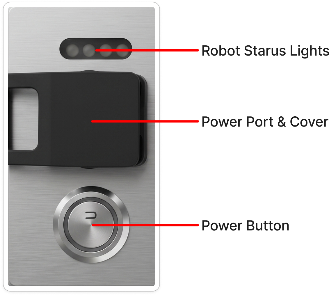
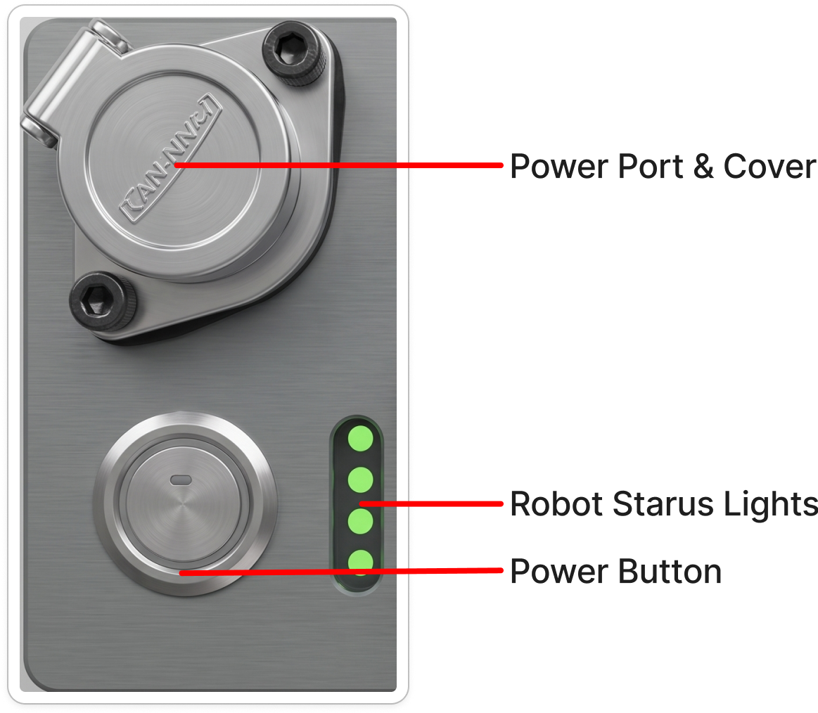
Both versions carry the same three elements — the power port with its cover, the power button, and the robot status lights — but lay them out differently.

Charging and power switch, version 1
Version 1
Charging and power switch, version 2
Version 2
ElementVersion 1Version 2
Power port coverHinged flip coverScrew-down round cover
Robot status lightsHorizontal strip above the power portVertical strip beside the power button
Power buttonBelow the power portBottom left, next to the status lights

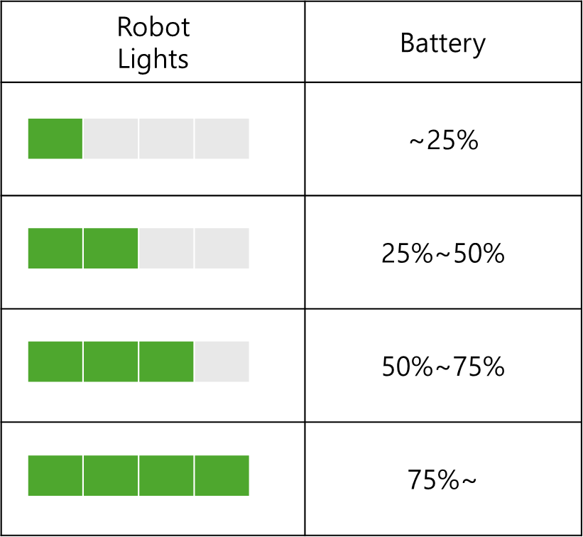
- Robot Battery Lights

Robot battery indicator lights

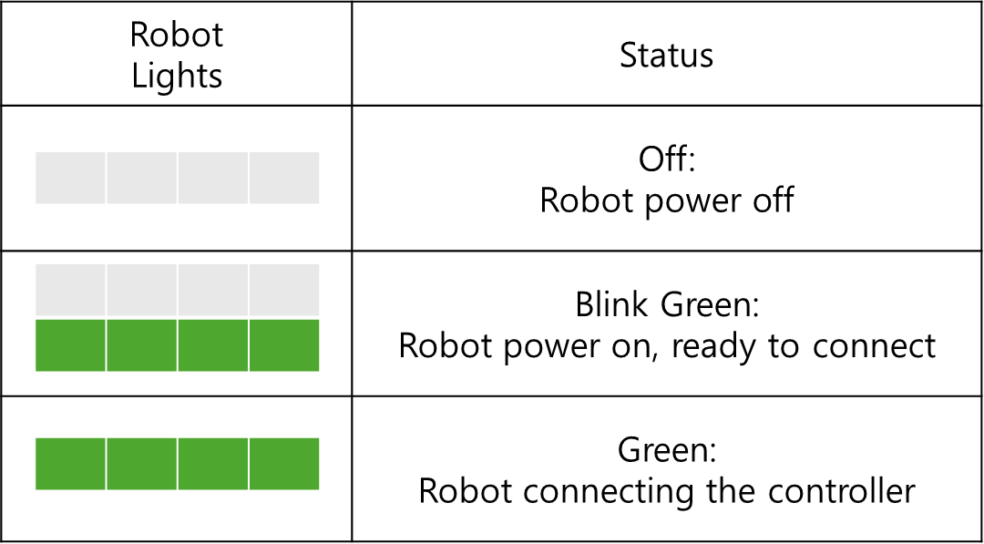
- Robot Status Lights (blinking)

Robot status indicator lights

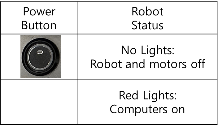
- Power Button Status

Power button status

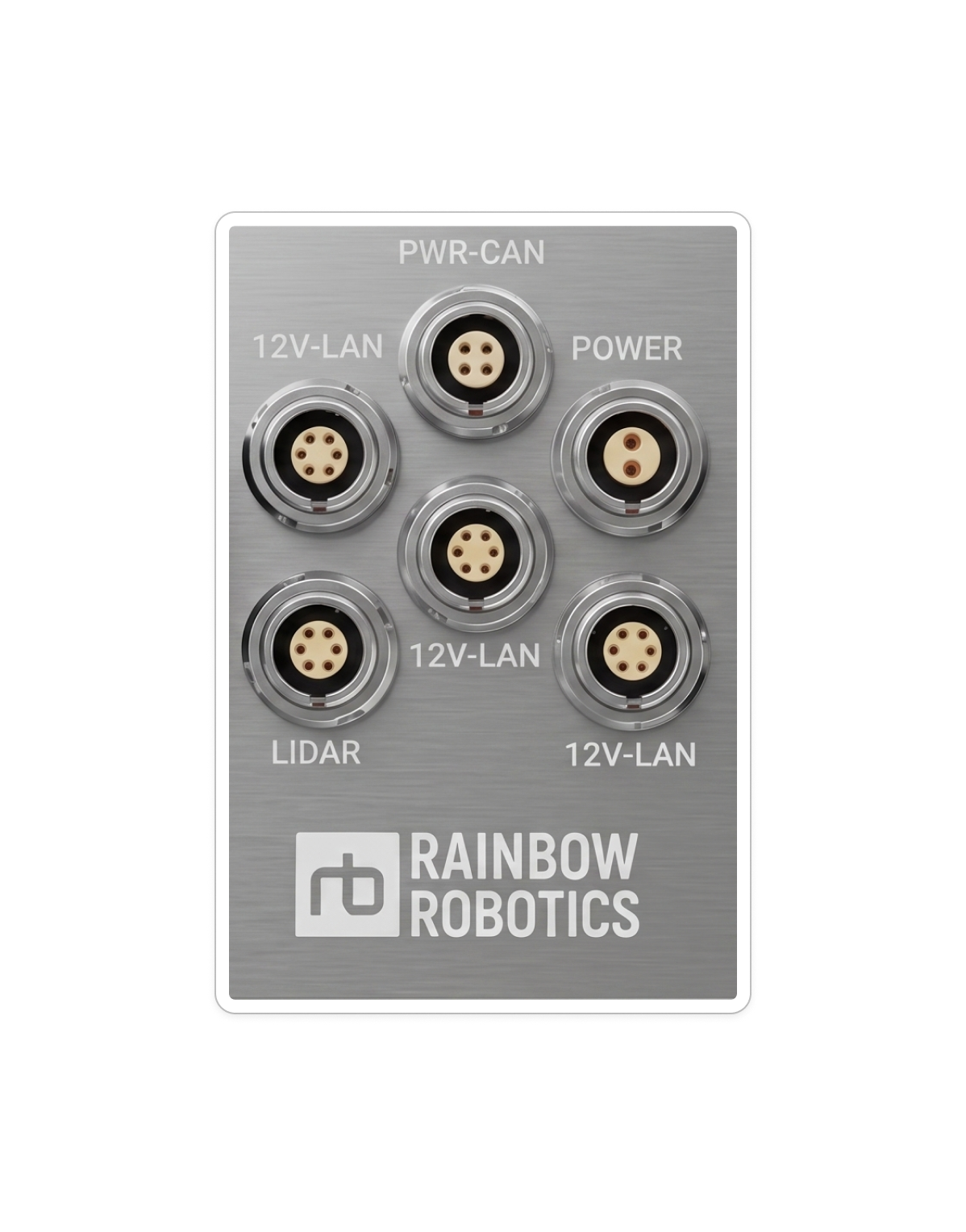
User Port Pin Map

The user ports differ between versions — see Ports by version for the full comparison. Pin maps for each port type follow below.

User ports, version 1
Version 1
User ports, version 2
Version 2

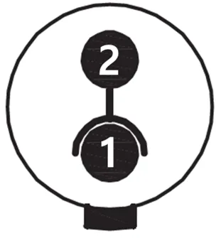
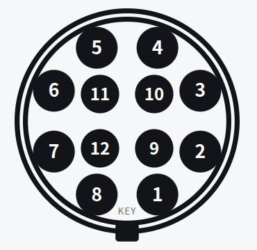
POWER

User port POWER pin map
PinFunctionColor
1VCCRed
2GNDBlack
  • VCC: 42.0 ~ 58.4V (Battery Power)
  • Max. Current: 5A


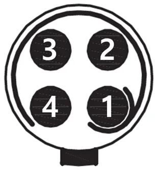
PWR-CAN

User port PWR-CAN pin map
PinFunctionColor
1VCCRed
2GNDBlack
3CAN HighWhite
4CAN LowBlue
  • VCC: 42.0 ~ 58.4V (Battery Power)
  • Max. Current: 10A
  • Can Communication is Connected to the Robot PC


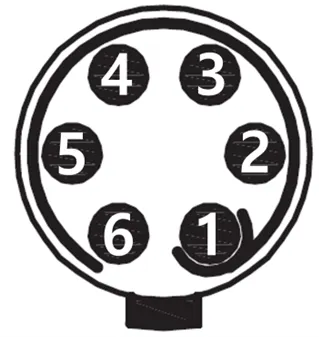
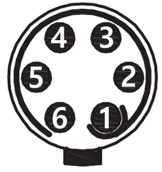
12V-LAN

User port 12V-LAN pin map
PinFunctionColor
1VCCRed
2GNDBlack
3LAN TX+White/Green
4LAN TX-Green
5LAN RX+White/Orange
6LAN RX-Orange
  • VCC: 12V
  • Max. Current: 2A
  • Network Switch Speeds: Fast Ethernet (100Mbps)
  • Lan Communication is Connected to the switching hub


LiDAR

Present on panel version 1 only. On version 2, LiDAR connects through a 12V/LAN port.

User port LiDAR pin map
PinFunctionColor
1VCCRed
2GNDBlack
3LAN TX+White/Green
4LAN TX-Green
5LAN RX+White/Orange
6LAN RX-Orange
  • VCC: 12V
  • Max. Current: 2A
  • Network Switch Speeds: Fast Ethernet (100Mbps)
  • Lan Communication is Connected to the User PC

Direct PC Port

Two USB-C ports connect straight to the onboard PCs. They are the same two ports on both versions; only the labels changed.

Direct PC ports, version 1
Version 1
Direct PC ports, version 2
Version 2
Connects toVersion 1Version 2
User PCVISIONU-PC
Robot PCMOTIONR-PC

This user manual is intended for RBQ users.