Skip to content

Leg module Attachment/Detachment

This manual explains the disassembly and assembly sequence of the RBQ10 leg module. The instructions are based on the front left leg, and since the other legs have a symmetrical structure, the same method should be used for the disassembly and assembly process.

Fastening specification

ParameterSpecification
Hex wrench4mm
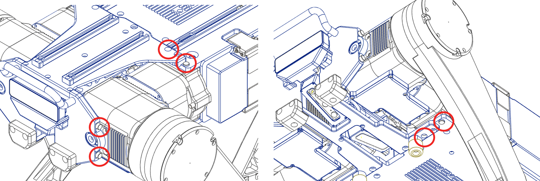
Q’ty6 bolts in total
Spring washerM5

Leg module disassembly

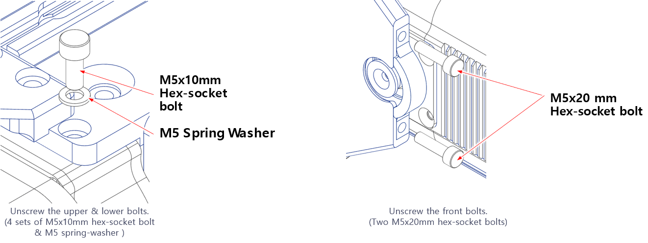
The bolts fastening the leg module are placed as shown below.

Leg module bolt layout

Step 1. Unscrew the bolts. (Dispose of the used M5 spring washers)

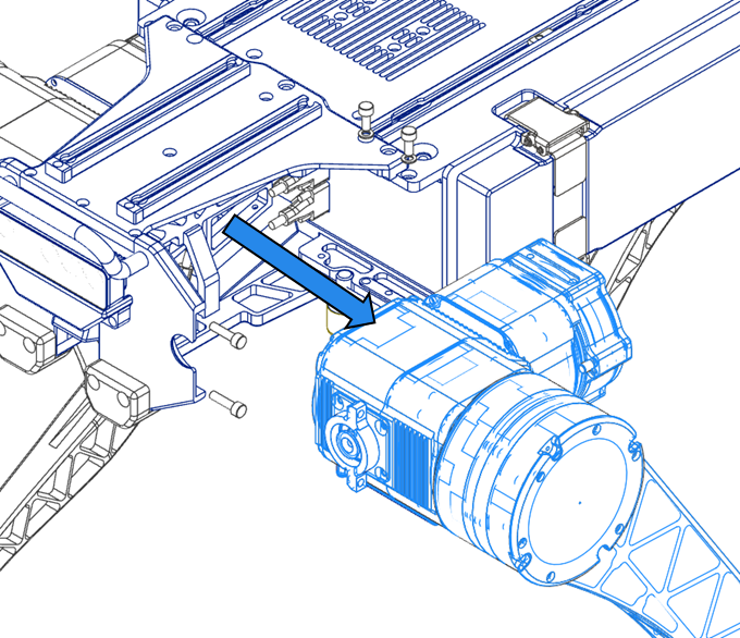
Step 2. Pull the leg module outward after the bolts are unscrewed.

CAUTION

Be careful not to damage the com-wire by pulling it too far.

Leg module removal

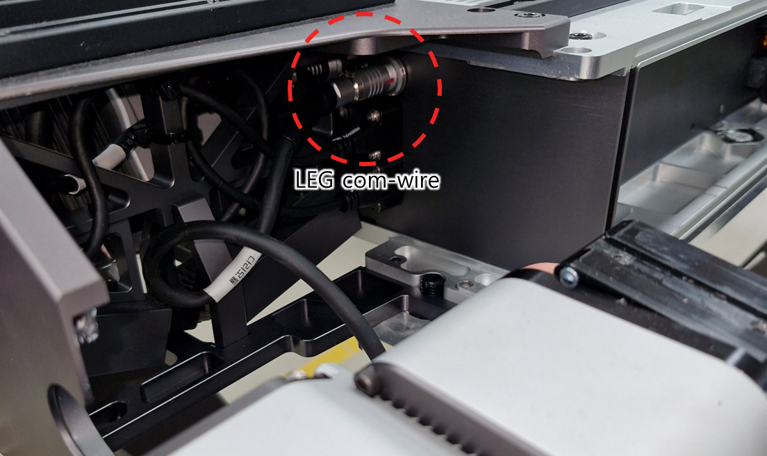
Step 3. Pull the connector handle to release the com-wire.

CAUTION

Pulling the com-wire directly may cause disconnection. Make sure to pull the handle.

Com-wire connector location
Com-wire released by pulling the handle

Leg module assembly

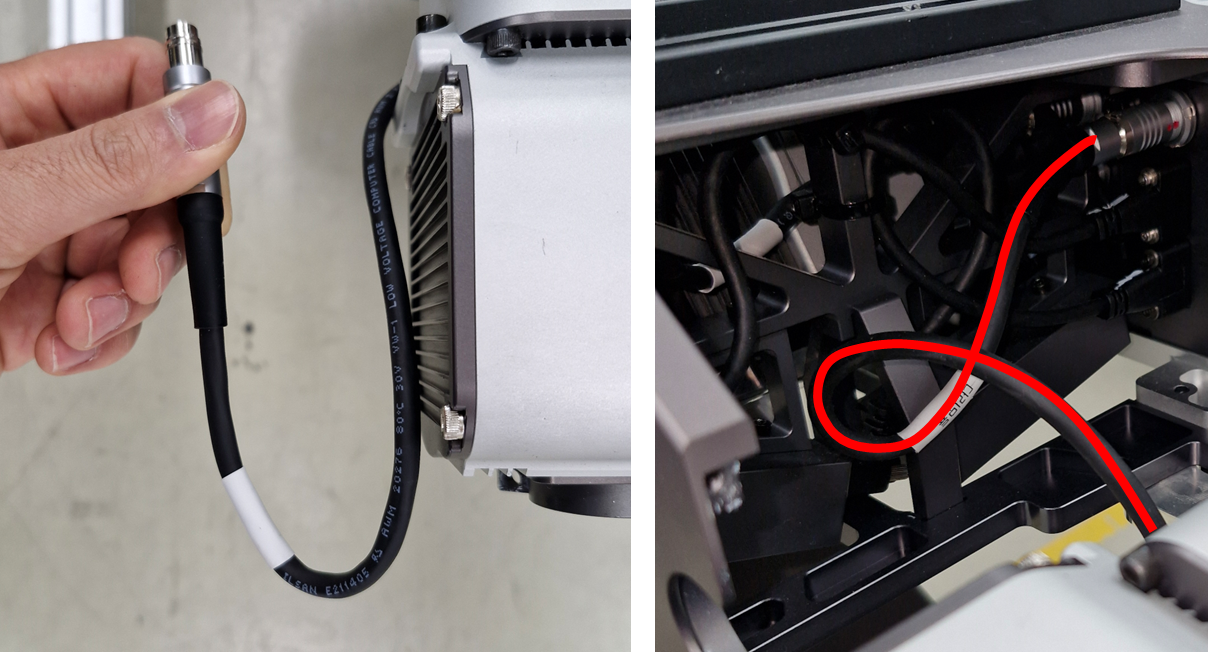
The leg com-wire must be coiled once before assembly. If it is assembled without coiling, the com-wire may get pinched and damaged between the leg and the upper and lower plates.

CAUTION

The spring washer for the bolts securing the leg is crucial for proper fastening. Be careful not to forget it during assembly.

Step 1. Coil the com-wire as shown in the picture below.

Coiling the com-wire

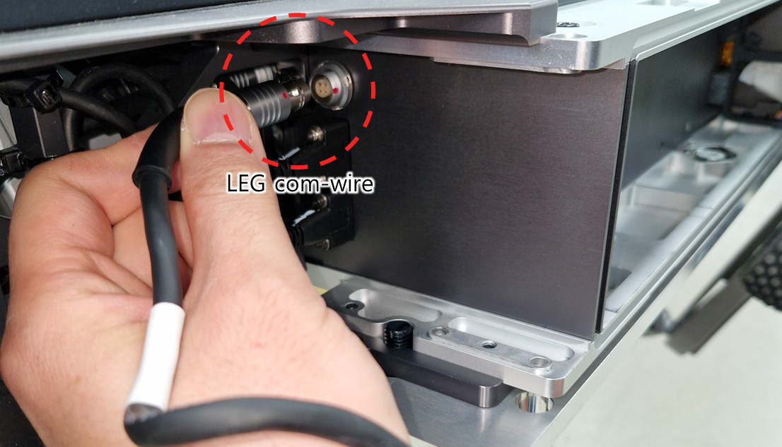
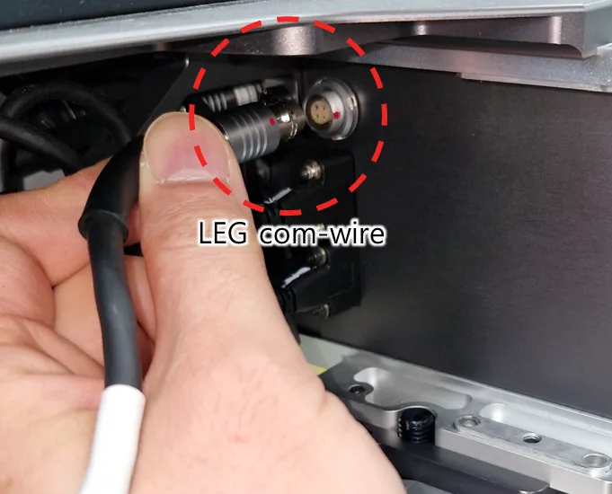
Step 2. Align the red dots and press firmly to connect the com-wire.

CAUTION

Pushing the com-wire may cause disconnection. Make sure to press the handle.

Connector mating

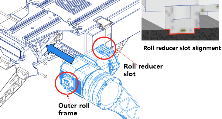
Step 3. Insert the roll frame and reducer slot into the body frame.

Insert roll frame

Step 4. Fasten the bolts. (Make sure to insert the M5 spring washers)

Tighten leg module bolts

This user manual is intended for RBQ users.