Skip to content

Maintenance ​

Open Maintenance with its tile on the hub. The tile is shown to everyone and opens even without a robot connected; the sections that act on the robot need it connected. The sections sit as chips across the top:

  • Everyone: Calibration, Robot Check, Software update (covered in Software Update).
  • Developer mode only: Power / System, Vision, Config file, and — on robots with an arm — Arm. These can cut the connection, drop the robot or change how its daemons start — read each warning before you press anything.

Calibration ​

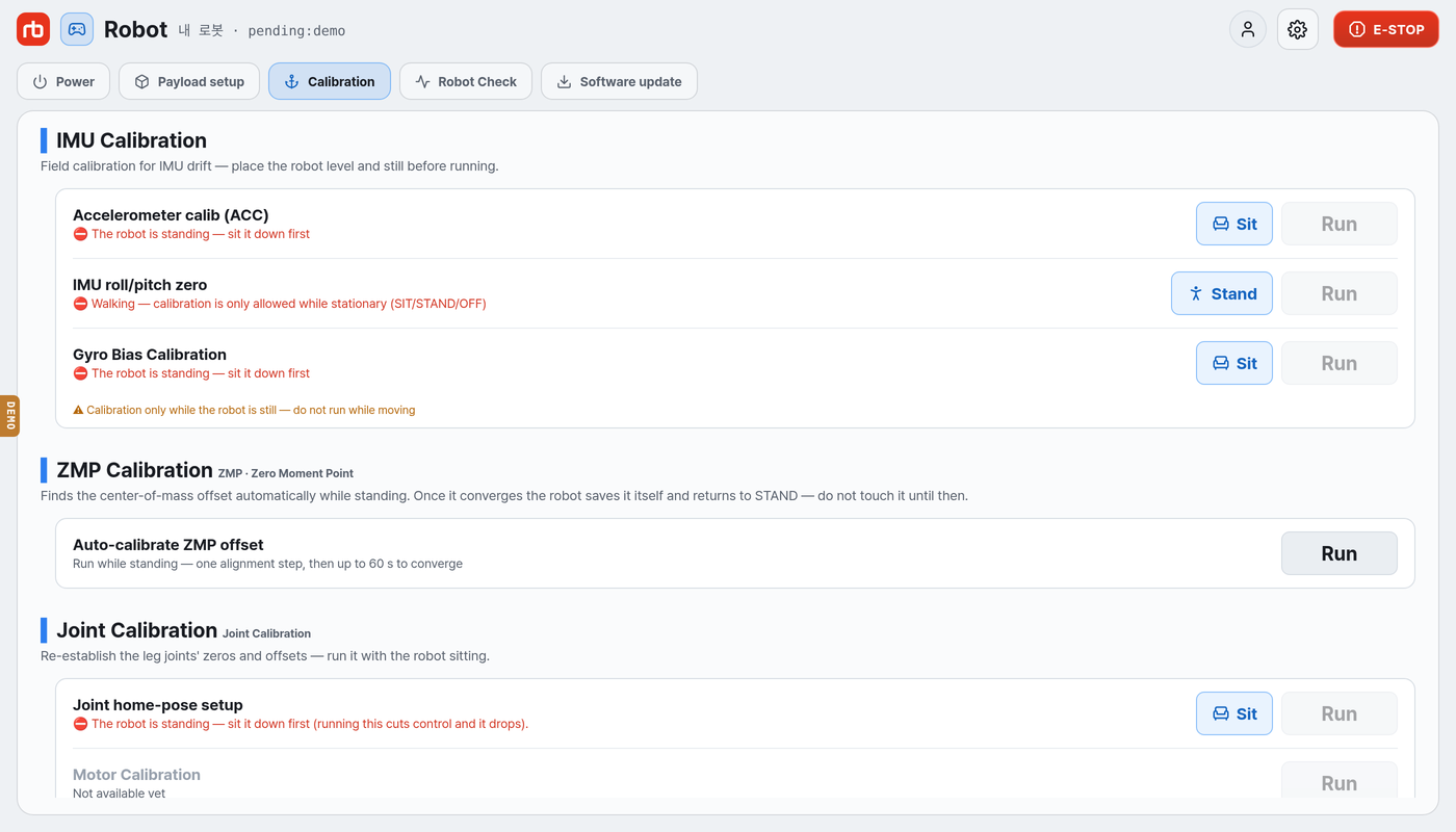
Calibration section

WARNING

Every calibration here must be run with the robot on flat ground and stationary. The IMU and ZMP rows are blocked while the robot is walking, has fallen, or is not reporting its state, and each one asks Run calibration? before it sends the command. Joint home-pose setup has its own confirmation. Do not touch the robot until the calibration has finished.

IMU Calibration ​

RowWhat it does
Accelerometer calib (ACC)Field correction of accelerometer drift. Run it while the robot is sitting, on level ground; it averages the gravity magnitude for about 2 s and stores the factor.
IMU roll/pitch zeroMakes the current posture the level reference. Takes about half a second — if the robot is tilted when you run it, all later control will be off.
Gyro Bias CalibrationResets the IMU, waits for the values to settle, then measures the gyro again — about 5 s, while the robot is sitting. When it finishes it reports all three axes and whether each one is within the limit. If the bias is still over the limit, hold the robot completely still and run it again.

Press Run, then confirm Run in the dialog. When a row is blocked, the app tells you why, and if it can clear the block itself, a button appears next to Run: Sit when the robot needs to sit, Stand when it needs to stand, and Auto Start when control is off, which asks first. You get no such button while the robot has fallen, is docking, or is not reporting.

IMU roll/pitch zero shows the current roll and pitch under the level in its dialog. A progress dialog follows while it runs. It ends with Success only when roll and pitch both come back within 1° — if the robot is still tilted, it reads The zero may not have taken effect instead, and you put the robot on flat ground and run it again.

ZMP Calibration ​

Auto-calibrate ZMP offset finds the center-of-mass offset automatically. The robot must be in STAND on flat ground. It walks one step to square up its legs, then takes up to 60 s to converge. Once the offset converges, the robot saves it on its own and returns to STAND. The panel shows the progress and a completion message.

Joint Calibration ​

Re-establishes the leg joints' zeros and offsets. Run it with the robot sitting.

RowWhat it does
Joint home-pose setupHold the home pose with the jig, then store it as the joint zero — four legs
DQ offset calibrationNot available yet — the row is reserved and cannot be pressed

Joint home-pose setup opens two dialogs: first the notice (This rewrites the joint zeros — running it without the jig, or with the pose off, leaves the robot booting on wrong zeros), then the per-leg screen. On that screen, pick the joints you want to set; the ones you pick move to the target pose in the 3D view on the left. Fit the jig, hold that pose, and press Save LEG{n} {g} home pose. Writing the zero switches control off (BOARD_RESET), so sit the robot down first — it will collapse if it is standing. The jig is required.

If the motor boards do not answer, the row is blocked with No communication with the motor boards — turn the 48 V drive (LEGS) power on and run it again; that rail is under Power / System on this page.

For the roll joint you pick the reference in the wizard: Limit pushes the joint against its inner limit as before, and Level 0° lets you make sure the body is level, set the joint to 0° with a bubble level, and shift the zero to match. Both references switch control off. The notice on closing offers Auto Start to bring the robot up again right away. If the correction is 9° or more, the robot rejects it and asks you to set the home against the limit first.

Camera Check · Calibration ​

RowWhat it does
Basic Camera CheckShows the views of the six cameras with their FPS. The views are not connected yet.
Lower Depth Camera On-chip CalibrationOpens the on-chip calibration notice for the lower depth cameras. Keep the robot standing on a flat floor. The calibration sequence itself is not available yet.
Lower Depth Camera Position CalibrationAsks you to install a marker board under the robot. The calibration itself is not available yet.

Docking calibration ​

The bottom of the Calibration section holds the auto-docking alignment parameters: Offset X (m), Offset Y (m), Req Count, Try Count.

  • Reload re-reads the values from the robot.
  • Defaults fills the fields with factory defaults — nothing is saved until you press Apply.
  • Apply writes the values to the robot and reads them back.

Robot Check ​

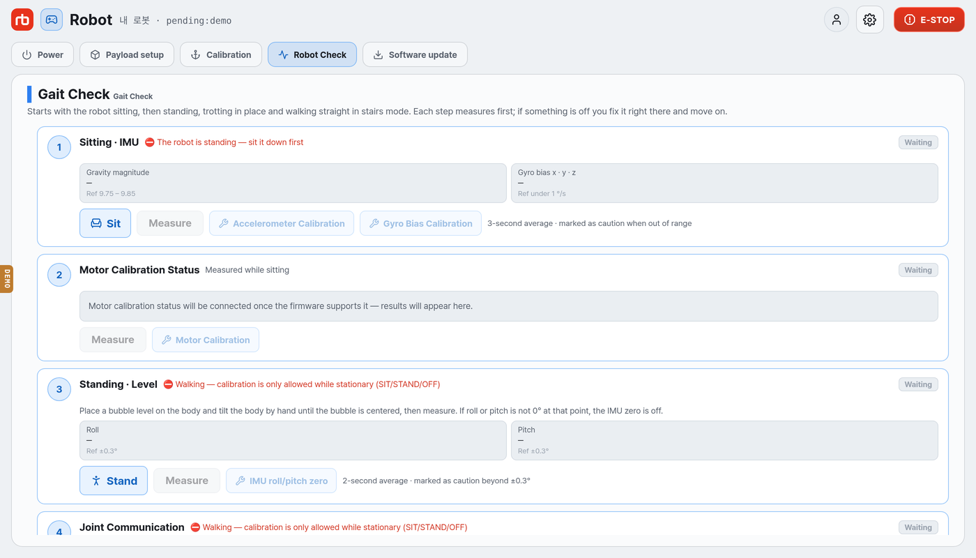
Robot Check section

Robot Check checks the robot's condition in order, from sitting to walking. Each stage is a card: press Measure, read the result, and if a value is out of range, fix it on the spot with the button next to it. The fix buttons work whether or not you have measured — they only follow the robot's state. An out-of-range value only marks the card Caution.

WARNING

Stages 4 and 5 move the robot by itself, and joystick input is ignored while they run. Clear 1 m around the robot before you start. Stop ends the run and the robot stands.

Gait Check ​

StageRobotWhat it measuresReferenceFix
1 Sitting · IMUSittingGravity magnitude and gyro bias, averaged over 3 s9.75 ~ 9.85 m/s², gyro under 1.0 °/sAccelerometer Calibration, Gyro Bias Calibration
2 Motor Calibration StatusSittingSupported in a later update——
3 Standing · LevelStandingRoll and pitch over 2 s, after you level the body by hand with a bubble level placed on it±0.3°IMU roll/pitch zero
4 Joint CommunicationStandingCAN communication of each joint while the body twists left and right up to 30°, five times (about 10 s) — Per motor: missed frames, lowest receive rate, longest receive gap; Per channel: Error frames, error-warning, error-passive, bus-off450 Hz or more received, gaps of 10 ms or less—
5 Trot in place · DriftStandingTrots in place for 10 s, stands again, and compares the body position with the startunder ±10 cm fore-aft, under ±5 cm lateralVisual Check, then Joint home-pose setup, then ZMP Calibration
  • Stage 4: if a joint is out of range, the card names the leg and asks you to check the wiring between the body and that leg module. Compare the missed frames between joints: a joint that misses frames while the others do not points to that leg's wiring. Per channel lists the CAN channels the legs are on, with the legs on each. Error frames counts how many times the channel reported a state change (error-warning, error-passive, bus-off or recovery) during the twist. These numbers are shown for reference and are not part of the verdict. The sim has no CAN measurement, so it is not judged there.
  • Stage 5: if the robot drifts 10 cm or more fore-aft or 5 cm or more sideways, the card marks every direction that drifted and recommends Visual Check, then Joint home-pose setup, then ZMP Calibration, in that order. The home-pose setup is the same wizard as in Calibration and needs the robot sitting — while it stands, a Sit button comes first.

Camera Check ​

There are three stages: Camera View · FPS, Depth Camera Quality, Depth Camera Alignment. Measuring and judging are not available yet; the fix buttons open the same dialogs as Calibration › Camera Check · Calibration.

Power / System ​

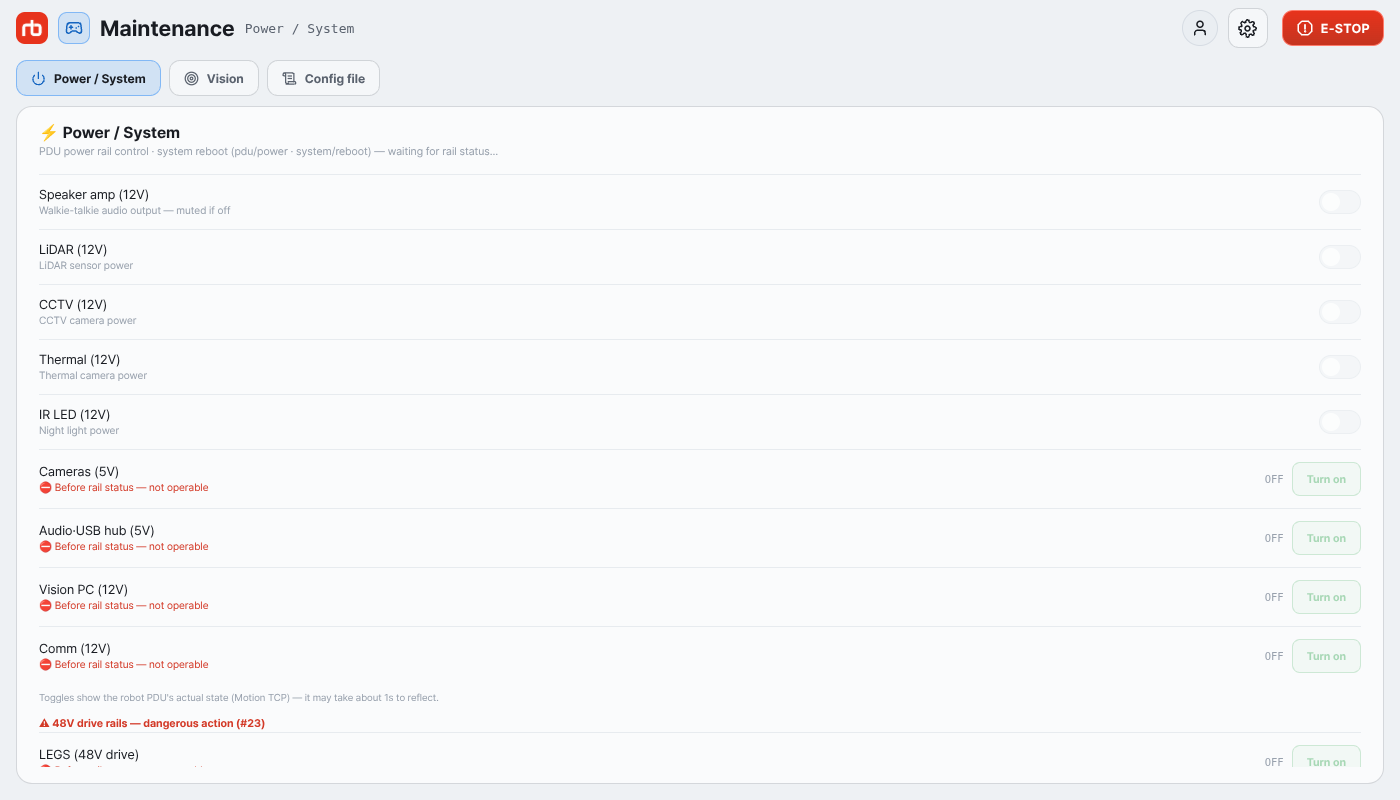
Power / System section

This section exposes every PDU rail, including the ones deliberately kept out of Settings. Toggles show the real rail state from the robot; they are disabled until that state has been received.

12 V toggles (one tap): Speaker amp (12V), LiDAR (12V), CCTV (12V), Thermal (12V), IR LED (12V).

Rails that break the link (two-step confirmation Turn this off? → Turn off; the dialog has a Don't ask for a day checkbox — once ticked, that rail switches without confirmation for 24 hours on this screen only; Settings → Power always confirms):

RailEffect of switching off
Cameras (5V)Video stops.
Audio·USB hub (5V)Audio devices disappear.
Vision PC (12V)Cameras, audio and part of the telemetry on this screen stop.
Comm (12V)The app's own connection to the robot is lost.

48 V drive rails (two-step, live voltage shown):

RailNotes
LEGS (48V drive)Leg motor power. Can only be switched off while the robot is not standing (sitting, control off or fallen); the row is blocked otherwise.
ARM · ADDON (48V)Arm and add-on power — one port for both. Confirm the arm is stopped first.
EXTERN (48V)External expansion port power.

DANGER

Switching LEGS (48V drive) off makes the robot collapse. System reboot — Reboot → Reboot the robot PC? → Reboot — restarts the robot PC: the robot loses motor power and the app connection drops for the duration. Sit the robot on the floor before either action. The reboot dialog also has the Don't ask for a day checkbox.

On CAN-FD robots the rails above are replaced by individual PDU ports in four groups — 12V ports, Camera power (USB), Audio, ⚠ 48V drive rails — dangerous action — each row showing its live state, voltage and current. Comm (12V · WAN), the camera ports and the 48 V ports confirm in two steps; LEGS (48V drive) is blocked while standing as above; PDU (48V battery rail) is display only. Inputs · Battery · Temperature below lists the charger inputs, both battery packs and the board temperatures.

Below the 48 V rails the section repeats the Accelerometer calib (ACC) and IMU roll/pitch zero rows described in Maintenance → Calibration; they behave the same here.

Vision ​

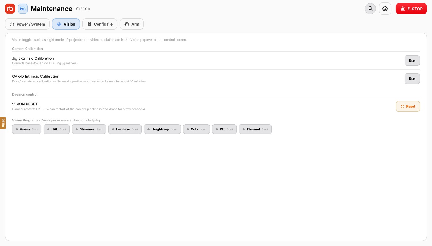
Vision section

Vision toggles — night mode, stealth, IR projector, video resolution and the rest — are in the Vision popover on the control screen; see Camera & Vision. This section holds the developer tools.

Camera Calibration:

RowWhat it does
Jig Extrinsic CalibrationCalibrates each sensor's base↔sensor transform from the jig markers. The robot must be seated on the calibration jig. The result is written to the HAL settings.
OAK-D Intrinsic CalibrationCalibrates the front and rear stereo cameras while walking. The front camera must face a ChArUco board within 1 m. The result is written to each camera's EEPROM.

Run opens a confirmation that lists what to check first; progress and the result appear in the top banner. While a calibration runs, both buttons change to Cancel.

WARNING

The OAK-D intrinsic calibration makes the robot walk around by itself for about 10 minutes. Keep 1.5 m around the robot clear before starting it.

Daemon control — VISION RESET → Reset has the Handler restart HAL, restarting the camera pipeline cleanly. Video drops for a few seconds; the button shows Resetting… and stays unavailable for about 8 seconds.

Vision Programs lets you start and stop individual vision daemons by hand (Vision, HAL, Streamer, Handeye, Heightmap, Cctv, Ptz, Thermal). Their on/off state comes from the robot's reported program status; only on older daemons that do not report it does it fall back to the last command sent.

Config file ​

Config file section

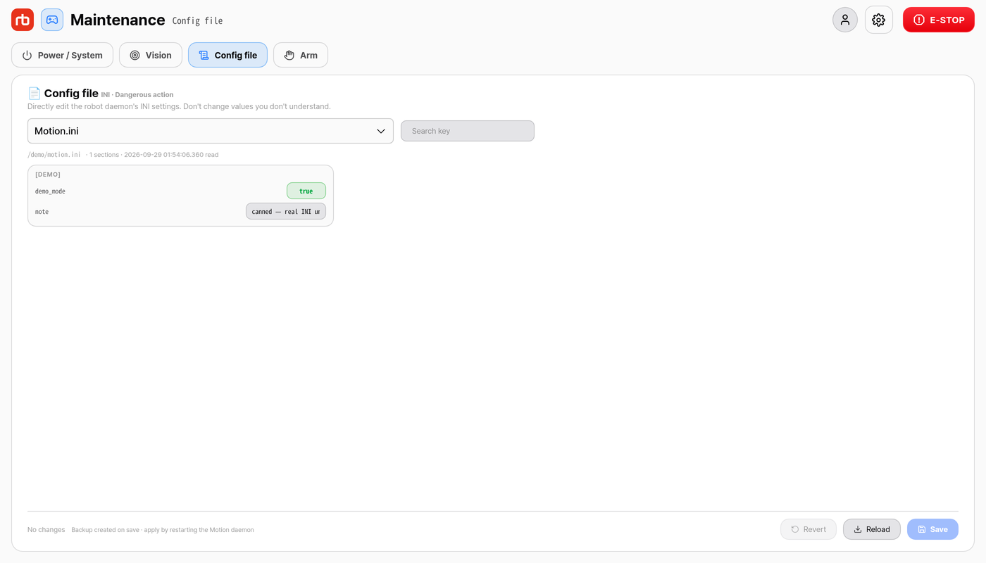
The INI editor edits the robot daemons' configuration files directly. The target selector switches between Motion.ini, HAL · config.ini, Handler · config.ini and Streamer.ini. Use Search key to filter keys; boolean values can be toggled, other values are edited in place. The header shows how many sections were read and when.

The footer counts unsaved edits ({n} changes). Revert discards them, Reload re-reads the file from the robot, Save opens the confirmation Save to {label}? listing every changed key with its old and new value.

WARNING

Saving replaces the entire file on the robot with what the editor holds — always edit on top of a freshly loaded file. Changes apply only after the corresponding daemon (Motion, HAL, Handler or Streamer) is restarted; the app does not restart it for you. Do not change values whose meaning you do not know.

Arm ​

Shown only when the robot reports an arm. This section is the initial bring-up.

  1. Press CAN check, Release brake, Control Start in that order. Wait for the status badge to light up after each step before pressing the next. ▶ Auto Start ARM runs the whole sequence in one press.
  2. Static poses sends a fixed pose (Straight, Folding, Ready, Lift, Packing, DoorReady) without a trajectory — on the first use start from Ready.
  3. Joint lock / jog — tap a joint card to lock or unlock it; hold + / − to jog a locked joint (the buttons are disabled while the joint is unlocked).

RC01 / RC02 attachment sections are not covered by this manual.

This user manual is intended for RBQ users.