Tool Flange Digital Input
Warning
- Before connecting RB Tool Flange I / O input port, the power should be cut off.
- The electrical drawing below is for Non-E type only.
1. Digital input internal circuit diagram
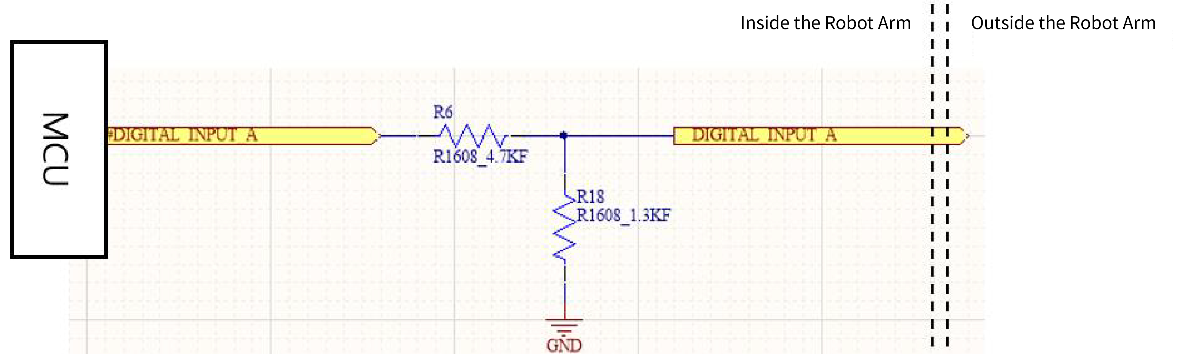
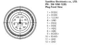
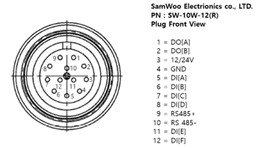
Device configuration for Tool Flange Digital input.
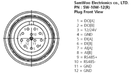
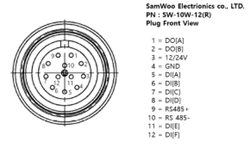
Exposed connector wiring diagram. The wiring diagram will be divided as shown above according to the robot version.
2. Digital input characteristics
| Terminals | Parameter | Min | Typ | Max | Unit |
|---|---|---|---|---|---|
| DIA, ... , DIF | Voltage | 0 | - | 24 | V |
| DIA, ... , DIF | OFF region | 0 | - | 9 | V |
| DIA, ... , DIF | ON region | 0 | - | 24 | V |
This is a specification that applies only to Tool Flange Digital input
(At this time, only DIA and DIB for Non-E version Robot are applied.)
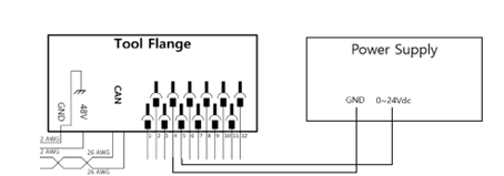
3. Test environment
Digital input device test was conducted using power supply, and the following configuration was tested.
4. How to use PNP sensor
(Ex source: https://blog.naver.com/mjg5080/97380010)
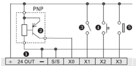
PNP sensor can be used in the same way as the above connection.
This applies equally to the Control Box Digital input.