General Purpose Analog I/O Configuration
The following methods are recommended for high reliability.
- Use analog GND closest to I/O.
- Equipment and control box use the same GND. Analog I/O is not isolated from the robot control box.
- Use shielded or twisted-pair cable. Connect to the GND shield on the Power (J12) terminal.
| Terminal | Parameter | Min | Type | Max | Unit |
|---|---|---|---|---|---|
| Voltage mode Input | |||||
| AIx - AG | Voltage | 0 | - | 10 | V |
| AIx - AG | Resolution | - | 16 | - | Bit |
| Voltage mode Output | |||||
| AOx – AG | Voltage | 0 | - | 10 | V |
| AOx – AG | Resolution | - | 16 | - | Bit |
1. Analog output
The analog output can be used to control speed of conveyor. The figure below illustrates a simple demonstration.

2. Analog input
The output value of the analog sensor can be used by the control box as analog input. The figure shown below illustrates a simple connection to an analog sensor.

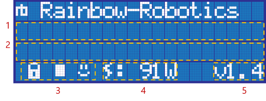
3. LCD Status Display

- Display Box(1): Displays information about system status.
- Please Wait: The main PC in the control box is booting up.
- default: The main PC in the control box is ready.
- Please Wait: The main PC in the control box is booting up.
- Display Box(2): Displays information about robot operation and status.
- Action Icon: Definition lock(
 ) or release(
 ) state, play(
 ) or stop(
 ) state, crash(
 ) or safe(
 )
)
state. - Power Consumption: Indicates the total power consumption in watts (W).
- System Version Information: System version information.
 Rainbow Robotics