Robot Arm
Names of Each Part
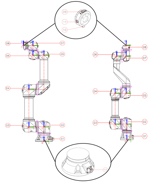
| No. | Name | Description |
|---|---|---|
| ① | Base | Part for securing the robot |
| ② | J0 : Base Joint | - |
| ③ | J1 : Shoulder Joint | - |
| ④ | J2 : Elbow Joint | - |
| ⑤ | J3 : Wrist 1 Joint | - |
| ⑥ | J4 : Wrist 2 Joint | - |
| ⑦ | J5 : Wrist 3 Joint | - |
| ⑧ | Tool Flange | Part for attaching a gripper or tool to the robot |
| ⑨ | Teaching Button | Button for direct teaching |
| ⑩, ⑪ | I/O Connector A(⑩), B(⑪) (Non E, E-Version : ⑩ / U-Version : ⑩,⑪) | Input/output ports for controlling the gripper or tool |
| ⑫ | Robot-Control Box Connector | Cable connection connector between the robot arm and control box |
Robot Arm Shape and Dimension Information
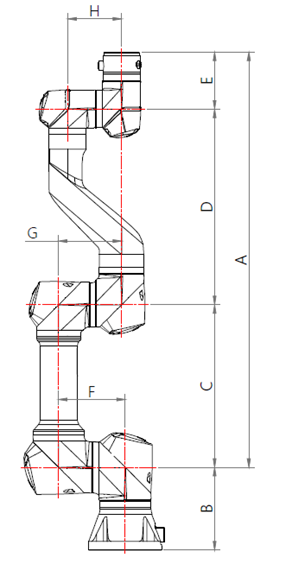 Unit (mm)
| Model | A | B | C | D | E | F | G | H |
|---|---|---|---|---|---|---|---|---|
| RB3-730ES Series | 730 | 145.3 | 286 | 344 | 100 | 117.15 | 110.7 | 94.6 |
| RB6-920ES Series | 920 | 165.5 | 400 | 423.3 | 96.7 | 151.4 | 129.2 | 110.7 |
| RB20-1900ES Series | 1900 | 241 | 885 | 885 | 130 | 254.5 | 187.5 | 129.2 |
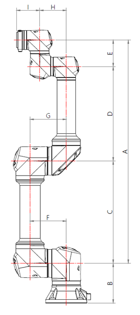 Unit (mm)
| Model | A | B | C | D | E | F | G | H | I |
|---|---|---|---|---|---|---|---|---|---|
| RB5-850E Series | 927.7 | 165.5 | 425 | 392 | 110.7 | 151.4 | 151.4 | 110.7 | 96.7 |
| RB3-1200E Series | 1200 | 165.5 | 566.9 | 522.4 | 110.7 | 151.4 | 151.4 | 110.7 | 96.7 |
| RB10-1300E Series | 1300 | 197 | 612.7 | 570.15 | 117.15 | 187.5 | 151.4 | 117.15 | 115.3 |
| RB16-900E Series | 900 | 197 | 412.7 | 370.15 | 117.15 | 187.5 | 151.4 | 117.15 | 115.3 |
Usage of RB5-850EA#, RB3-1200EA#, RB10-1300EA#, RB16-900EA#, RB6-920ESA#, RB20-1900ESA# (Pneumatic/Electric Cable Built-in Models)
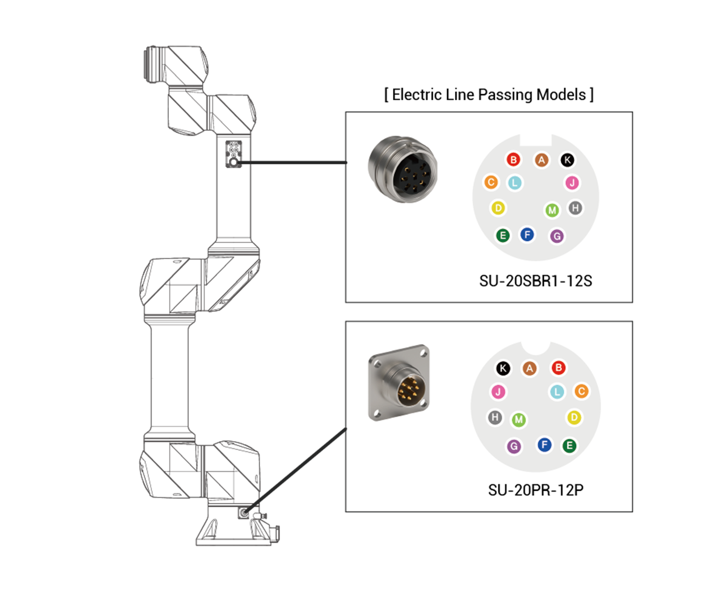
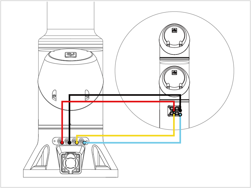
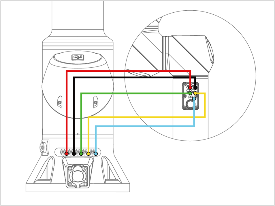
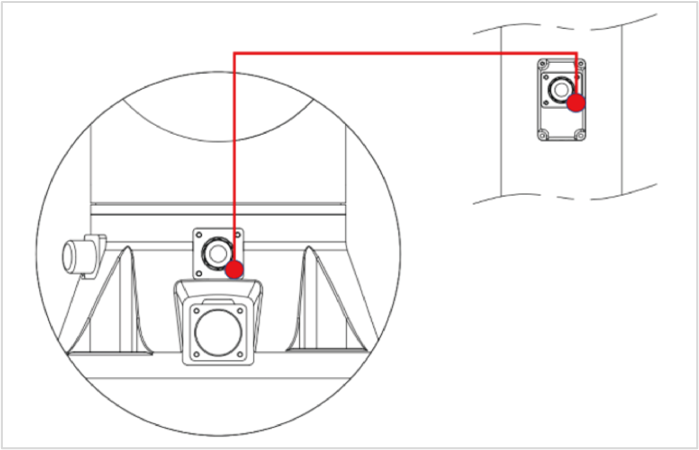
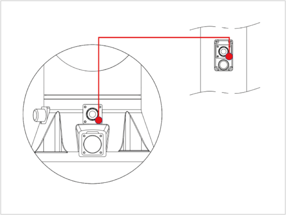
- The pneumatic and electric lines of models RB5-850EA#, RB3-1200EA#, RB10-1300EA#, RB16-900EA#, RB6-920ESA#, and RB20-1900ESA# are provided as shown in the table below. Please refer to the diagram for usage.
| Model | Pneumatic Line | Electric Line |
|---|---|---|
| RB5-850EA1 | Up to 4 (4∅ pneumatic tubes) | None |
| RB5-850EA2 | Up to 5 (4∅ pneumatic tubes) | 12-pin (AWG28) |
| RB3-1200EA1 | Up to 4 (4∅ pneumatic tubes) | None |
| RB3-1200EA2 | Up to 5 (4∅ pneumatic tubes) | 12-pin (AWG28) |
| RB10-1300EA1 | 1 (8∅ pneumatic tubes) | None |
| RB10-1300EA2 | 1 (8∅ pneumatic tubes) | 12-pin (AWG28) |
| RB10-1300EA3 | Up to 4 (4∅ pneumatic tubes) | None |
| RB16-900EA1 | Up to 4 (4∅ pneumatic tubes) | None |
| RB16-900EA2 | 1 (8∅ pneumatic tubes) | None |
| RB6-920ESA1 | Up to 4 (4∅ pneumatic tubes) | None |
| RB20-1900ESA1 | Up to 4 (4∅ pneumatic tubes) | None |
| RB20-1900ESA2 | 1 (8∅ pneumatic tubes) | None |
- The number of pneumatic lines should be adjusted after checking the operating range.
WARNING
- For pneumatic/electric cable built-in models, passing pneumatic pressure or power beyond the defined specifications may damage the hardware.
Robot Arm LED Status
< The LED status shown in the image below indicates that the robot is in Real Robot mode.>
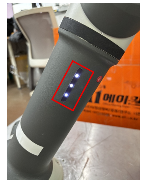
1. When only one of the three LEDs is lit,
it indicates that power is being supplied to the robot arm.
2. When two of the three LEDs are lit,
it indicates that the robot arm has completed booting and is in Simulation mode.
3. When all three LEDs are illuminated,
it indicates that the robot arm is in Real Robot mode.
4. When all three LEDs are blinking,
it indicates that a program is running.