Tool Connection
Secure the tool to the tool flange using four M6 bolts(Standard: ISO 9409-1-50-4-M6).
- Tools and M6 bolts are not included in the product.
- The connection methods may be different between tools. Please contact the tool manufacturer for further details.

- After fixing the tool to the tool flange, connect the necessary cables to the I/O ports on either the tool I/O or the control box I/O.
- The specifications of the I/O connector located in the tool flange vary depending on the robot model.
1. Non-E, E Version

- I/O connector A : Sam Woo Electronics/M12 x P0.5 female circular connector, 12pin/SW-10W-12(P)
| Port | Layout (Robot Side) | Pin No. | Signal (Non-E Version) | Color (Thickness) | Signal (E Version) | Color (Thickness) |
|---|---|---|---|---|---|---|
| Tool I/O |  | 1 | Digital Output A | Brown (AWG22) | Digital Output A | White (AWG25) |
| 2 | Digital Output B | Blue (AWG22) | Digital Output B | Black (AWG25) | ||
| 3 | 0/12/24 VCC | Red (AWG22) | 0/12/24 VCC | Red (AWG25) | ||
| 4 | Ground | Black (AWG22) | Ground | Green (AWG25) | ||
| 5 | Digital Input A | White (AWG22) | Digital Input A | Yellow (AWG25) | ||
| 6 | Digital Input B | Blue (AWG26) | Digital Input B | Brown (AWG25) | ||
| 7 | Analog Input A | Yellow (AWG26) | Digital Input C | Blue (AWG25) | ||
| 8 | Analog Input B | Red (AWG26) | Digital Input D | Gray (AWG25) | ||
| 9 | RS485+ | Gray (AWG26) | RS485+ | Orange (AWG25) | ||
| 10 | RS485- | Purple (AWG26) | RS485- | Purple (AWG25) | ||
| 11 | Common Ground | Black (AWG26) | Digital Input E | Pink (AWG25) | ||
| 12 | Common Ground | Green (AWG26) | Digital Input F | Natural Color (AWG25) |
2. U Version
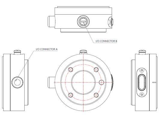
- I/O connector A : Binder / M8 male panel mount connector, 8pin / 76 6319 1111 00008-0200
- I/O connector B : Binder / M8 female panel mount connector, 8pin / 76 6618 1111 00008-0200
| Port | Layout (Robot Side) | Pin No. | U Version A Port | U Version B Port | Color (A=B) |
|---|---|---|---|---|---|
| Tool I/O |   | 1 | D+(RS485+) | NC | White |
| 2 | D-(RS485-) | NC | Brown | ||
| 3 | Digital Input 1 (PNP) | Digital Input 3 (PNP) | Green | ||
| 4 | Digital Input 0 (PNP) | Digital Input 2 (PNP) | Yellow | ||
| 5 | Power(+) | Power(+) | Grey | ||
| 6 | Digital Output 1 (PNP) | Digital Input 5 (PNP) | Pink | ||
| 7 | Digital Output 0 (PNP) | Digital Input 4 (PNP) | Blue | ||
| 8 | Ground (-) | Ground (-) | Red |
Non-E version, E Version, and U Version have different tool flange specifications.
[Common Content] Internal power supply can be set to 0V, 12V, and 24V on the I/O tab of the GUI.
- Min Nominal Max Unit Supply voltage in 24V mode - 24 - V Supply voltage in 12V mode - 12 - V Supply current in both modes - - 2000 mA [Non-E Version] The tool digital output is applied in the NPN method, when the digital output is enabled, the connection of the port leads to a ground (GND).
When disabled, the output port is open (open-collector/open-drain), the electrical specifications are as follows.Non-E Version Min Nominal Max Unit Open voltage 0 - 24 V Current via GND 0 - 2000 mA [E, U Version] The tool digital output is applied in the PNP method, when the digital output is enabled, the connection of the port leads to the VCC.
When disabled, the output port is open (open-collector/open-drain), the electrical specifications are as follows.E, U Version Min Nominal Max Unit Open voltage 0 - 24 V Current via VCC 0 - 50 mA
3. Non-E Version Usage Examples
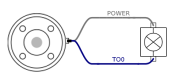
- The image shown below illustrates how to turn on/off a load with 12V or 24V. The voltage level can be specified in the Tool Out block.
TIP
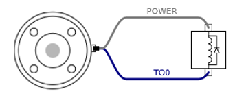
It is strongly recommended to use a diode to protect the tool using an inductive load.
The tools digital inputs use PNP and pull-down resistors. Therefore, when the input port is not connected (floating), the corresponding input port is read as low (0). Electrical specifications are as follows.
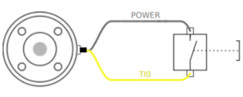
- Min Nominal Max Unit Input Voltage 0 - 24 V Logic Low-Voltage - - 9 V Logic High-Voltage 10 - - V The figure shown below illustrates how to use the digital input for a simple switch.
The tool analog input measures the voltage in a non-differential manner. The measurement categories are as follows.
- Min Nominal Max Unit Input Voltage 0 - 10 V Resolution - 12 - bit The figure below shows how to connect an analog sensor with non-differential voltage output characteristics to the tool flange.
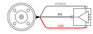
The figure below shows how to connect an analog sensor with differential voltage output characteristics to the tool flange.
Connecting the negative output of the sensor to GND (ground) works the same as the non-differential light sensor.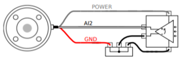
4. E Version, U Version Usage Examples
To use the tool digital output, the load is turned on using a 12V or 24V power supply as shown below.
You can define the output voltage in the Tool Out block.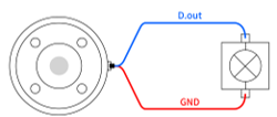
TIP
It is strongly recommended to use a diode to protect the tool using an inductive load.
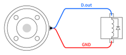
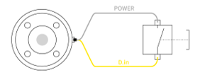
The tool digital input is applied in the PNP manner. Therefore, if there is no connection to the input terminal (floating), the input port is read as Low, 0). The electrical specifications are as follows.
- Min Nominal Max Unit Input Voltage 0 - 24 V Logic Low-Voltage - - 3 V Logic High-Voltage 4 - - V To use the tool digital input, the figure below shows how to connect simple buttons.
E Version and U Version do not support tool analog input.
Caution
- For further details regarding technical specification and wire connection, please refer to Appendix D.
- The cross-sectional view related to the tool flange is illustrated in Appendix C.
The tool flange supports RS485 serial communication and supports the following serial communication standard.
| Baud-Rate | 9600, 19200, 38400, 57600, 115200, 1M |
|---|---|
| Stop Bit | 1,2 |
| Parity | None, Even, Odd |
 Rainbow Robotics