Set-up (I/O 1)
Here is where you can configure the functions of the GPIO ports on the control box.
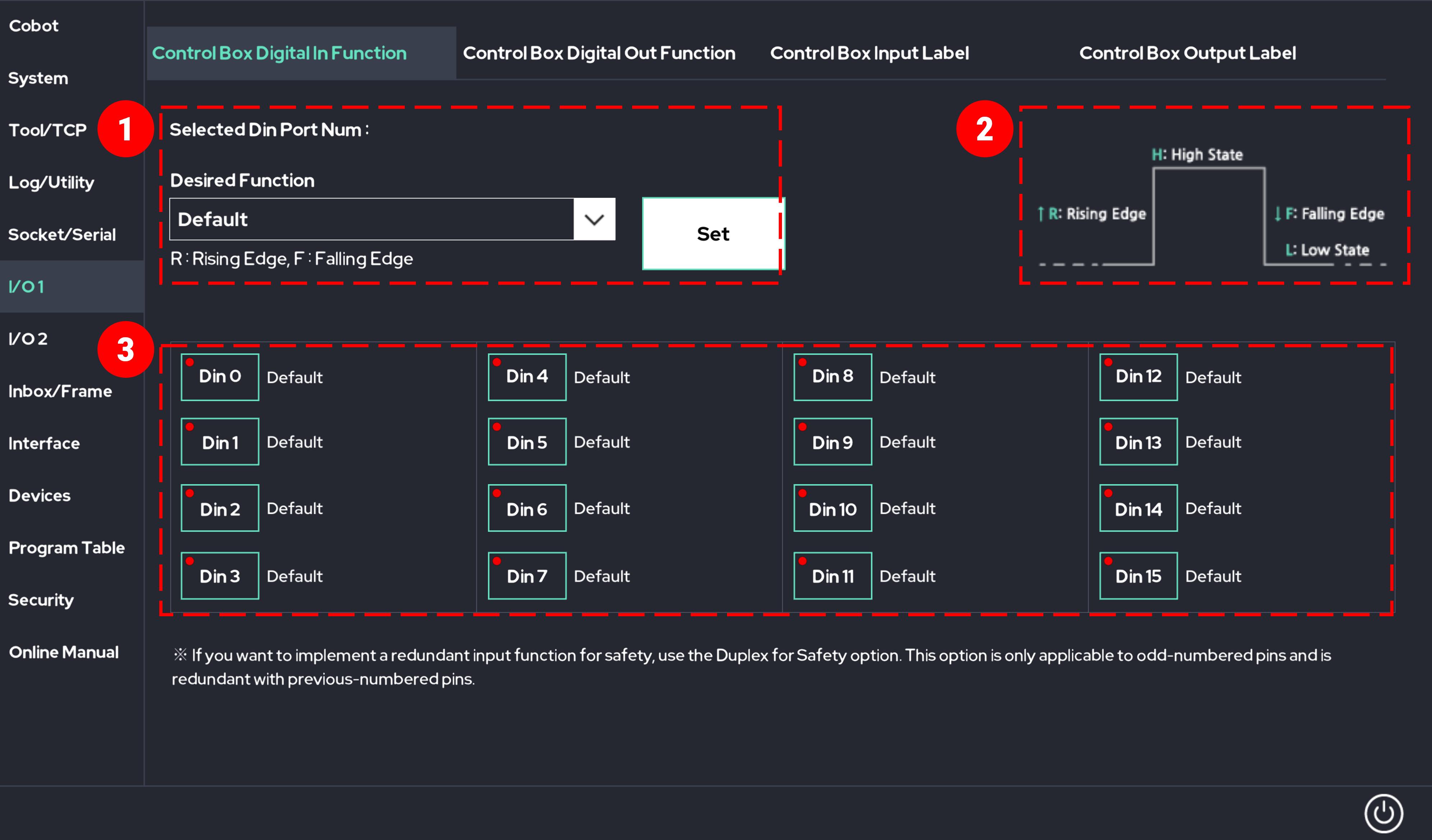
1. Control Box Digital Input Function Definition

- Select the input port for which you want to change the function.
- R : The function applied to the selected digital input port is activated when the digital input pulse is at the Rising Edge.
- H : The function applied to the selected digital input port is activated when the digital input pulse is at the High State.
- F : The function applied to the selected digital input port is activated when the digital input pulse is at the Falling Edge.
- L : The function applied to the selected digital input port is activated when the digital input pulse is at the Low State.
- R : The function applied to the selected digital input port is activated when the digital input pulse is at the Rising Edge.
- The functions applied to the 16 digital input ports are displayed.
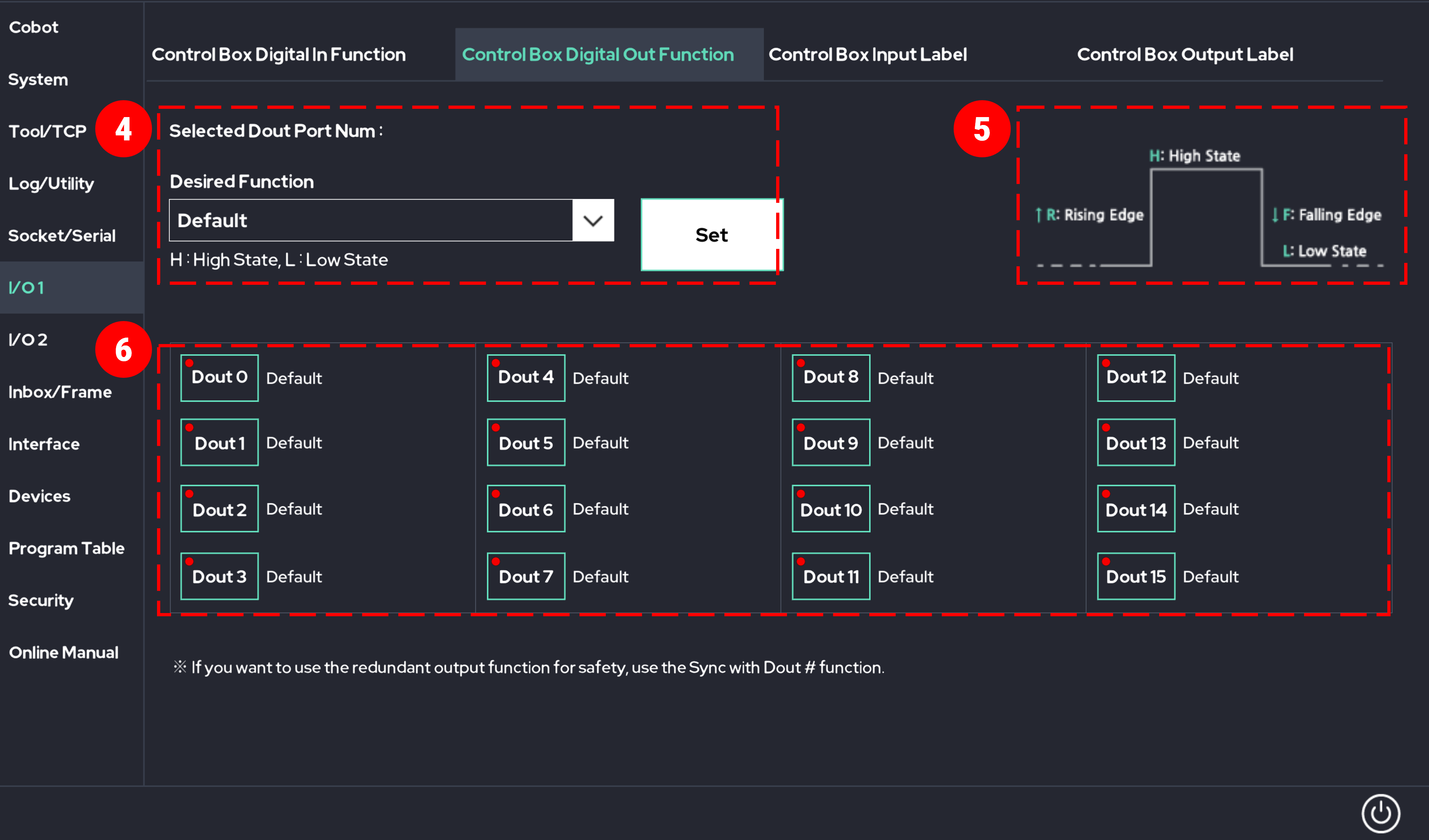
2. Control Box Digital Output Function Definition

- Select the output port for which you want to change the function.
- R : The function applied to the selected digital output port is activated when the digital output pulse is at the Rising Edge.
- H : The function applied to the selected digital output port is activated when the digital output pulse is at the High State.
- F : The function applied to the selected digital output port is activated when the digital output pulse is at the Falling Edge.
- L : The function applied to the selected digital output port is activated when the digital output pulse is at the Low State.
- R : The function applied to the selected digital output port is activated when the digital output pulse is at the Rising Edge.
- The functions applied to the 16 digital output ports are displayed.
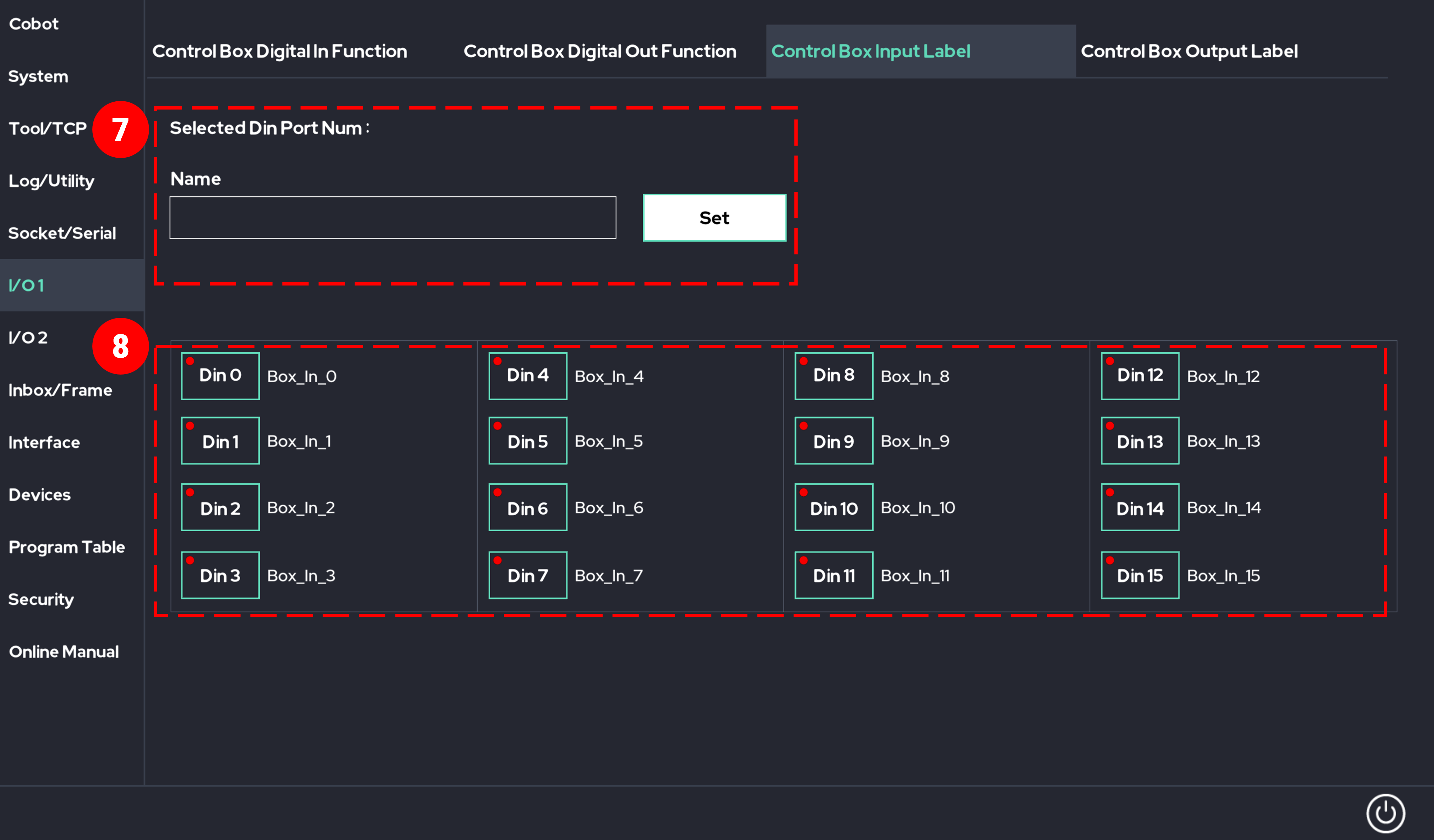
3. Control Box Input Labels

- Enter the desired name.
- Select the input port for which you want to set the name.
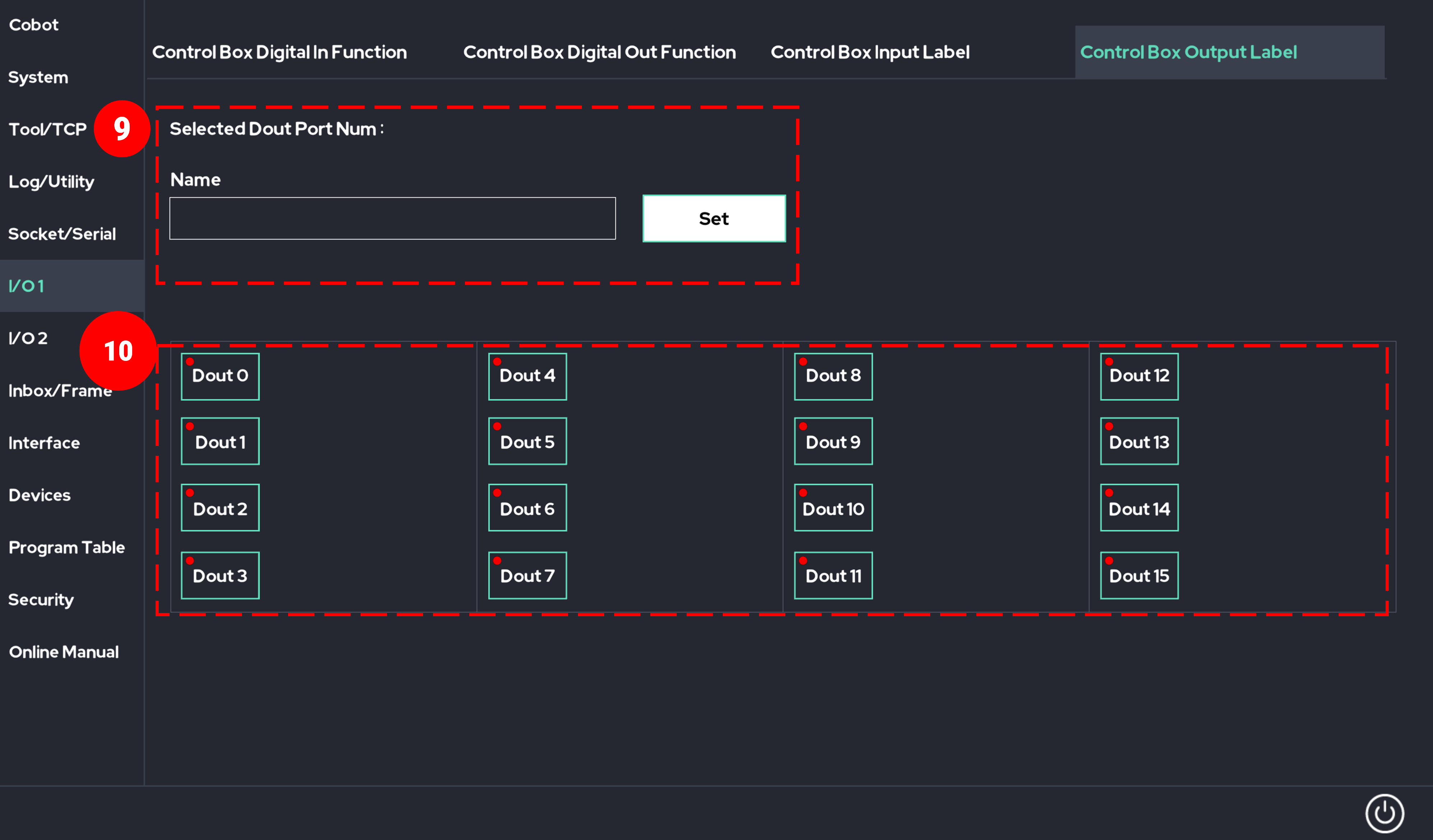
4. Control Box Output Labels

- Enter the desired name.
- Select the output port for which you want to set the name.
5. Control box input port functionality
The functions of the input ports (Din 0 to Din 15) in the control box can be set to the following special functions (R = Rising Edge, F = Falling Edge, H = High State).
Caution
- Before using Digital Input, be sure to fully understand the electrical characteristics of the digital input port provided by the manufacturer.
- Basic Mode (GPIO)
- Start Program Once Mode (Rising Edge)
- Stop Program (Rising Edge)
- Pause Program (Rising Edge)
- R = Turn on Direct Teaching Mode / F = Turn off Direct Teaching Mode
- R = Set Speed to 100% / F = Set Speed to 0%
- R = Switch to Real Mode / F = Switch to Simulation Mode
- R = Reset Robot
- H = Disable Collision Function when in High State
- H = Auto Initialization Key
- R = Release Pause due to External Collision
- R = Add Point Function to UI Program (Rising Edge)
- R = Start Program in Repeat Mode (Rising Edge)
- R = Move to Begin Position
- R = Resume Program
- H = Quick Freedrive Change
- R = Pause Program / F = Resume Program
- F = Pause Program / R = Resume Program
- H = Speed Slider at 100% / L = Speed Slider at 0%
- R = Load Default Program
- F = Turn Off Robot Arm Power
- R = Touch Sensing
- F = Touch Sensing
- H = No Arc
- H = Program Start Block
- R = Ext.Joint0 Plus / F = stop
- R = Ext.Joint0 Minus / F = stop
- R = Ext.Joint1 Plus / F = stop
- R = Ext.Joint1 Minus / F = stop
- R = Ext.Joint2 Plus / F = stop
- R = Ext.Joint2 Minus / F = stop
- H = Safety Speed
- F = UserCoord0 ←TCP frame
- F = UserCoord1 ←TCP frame
- F = UserCoord2 ←TCP frame
- F = Load & Run Program Table
- R = Start Prog.(Once) / F = Stop Prog.
- R = Start Prog.(Repeat) / F = Stop Prog.
- F = Change Global Pinpoint #’s Prog.
- R = EXT. Joint 0 Slow Plus / F = Stop
- R = EXT. Joint 0 Slow Minus / F = Stop
- R = EXT. Joint 1 Slow Plus / F = Stop
- R = EXT. Joint 1 Slow Minus / F = Stop
- R = EXT. Joint 2 Slow Plus / F = Stop
- R = EXT. Joint 2 Slow Minus / F = Stop
- R = Reset SOS
- F = Reset SOS
- R = Delete Point
- R = Add ARC-ON
- R = Add ARC-Off
- H = Speed 75% / L = 0%
- H = Speed 50% / L = 0%
- H = Speed 25% / L = 0%
- H = Speed 10% / L = 0%
- F = Pause Program
- H = Block Freedrive Button
- L = Block Freedrive Button
- Duplex for Safety
- F = Stop Program
6. Control box output port functionality
The functions of the output ports (Dout 0 to Dout 15) of the control box can be set to the following special functions (R = Rising Edge, F = Falling Edge, H = High State).
Output ports set to special features are not available for general use in teaching programs.
Caution
- Before using the digital output, be sure to fully understand the electrical characteristics of the digital output port provided by the manufacturer.
- Basic Mode (GPIO)
- H = Program/Robot Running / L = Idle State
- L = Program/Robot Running / H = Idle State
- H = External Impact Detected
- H = Direct Teaching Mode Active
- Transmit the digital input signal with the same number as the selected port
- Transmit Tool Flange Input Port 0 Signal
- Transmit Tool Flange Input Port 1 Signal
- H = Robot Active / L = Not Active
- H = Real Mode / L = Simulation Mode
- H = Robot in Operation / L = Idle
- L = Robot in Operation / H = Idle
- H = Robot Initialization (Activation) Failed
- H = Power Supplied to Robot Arm / L = No Power to Arm
- H = Collision Detection On / L = Collision Detection Off
- H = Pause State
- H = Trap Occurred in Inbox 0
- H = Trap Occurred in Inbox 1
- Used as PWM Module
- H = Teaching Pendant Connected
- H = Program Running in MAKE Screen
- H = Program Running in PLAY Screen
- H = Conveyor Mode Active
- H = Control Box Boot Complete
- H = Force Control Mode Active
- PC Alive Pulse
- H = Speed Slider at 100%
- H = Last Program Load Successful
- H = TCP is in InBox 0
- H = TCP is in InBox 1
- H = Is Alarm
- H = Robot posture is Begin posture
- H = Emergency Teaching Enable
- H = Prog. Run in Sub.P area
- H = Normal Program Run / L = Others
- H = Normal Program Run / H = Others
- H = Hand Controller F1 pressed
- H = Hand Controller F2 pressed
- H = Hand Controller F3 pressed
- H = Hand Controller F4 pressed
- L = TCP is in InBox 0
- L = TCP is in InBox 1
- Sync with Dout 0
- Sync with Dout 1
- Sync with Dout 2
- Sync with Dout 3
- Sync with Dout 4
- Sync with Dout 5
- Sync with Dout 6
- Sync with Dout 7
- Sync with Dout 8
- Sync with Dout 9
- Sync with Dout 10
- Sync with Dout 11
- Sync with Dout 12
- Sync with Dout 13
- Sync with Dout 14
- Sync with Dout 15
- H = Is SOS State
- L = Is SOS State
- H = EMG Button Released / L = Pressed
- L = EMG Button Released / H = Pressed
- L = Robot Speed under 250mm/s
- H = Robot Speed under 250mm/s
- H = Near Joint Limit
- H = Robot Arm under Activating
- H = Under Program Loading
 Rainbow Robotics