Operation Utilities
On the right side of the Make screen, there are other utility functions to help a user operate the system.
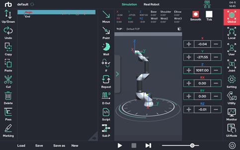
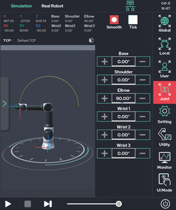
- Setting: Allows the user to use the jog function, as well as other utility functions to help the user’s experience.
- Utility: A collection of additional functions, such as the posture saving function, the system input / output information view function, and the system output test function. These functions are also frequently used.
- Monitor: Provides a window that allows the user to monitor both system and user variables in real time.
- UI Mode: UI mode can be selected according to the user's level and the user's purpose.
Utility sub-functions
1. Posture
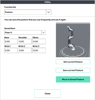
Up to 20 frequently used postures can be saved and used on the UI tablet.
Press the 'Get current Posture' button to get the current position information and press the Set button to save it.
Hold down the 'Move to Saved Posture' button to move to the saved position.
2. Move Joint to Origin
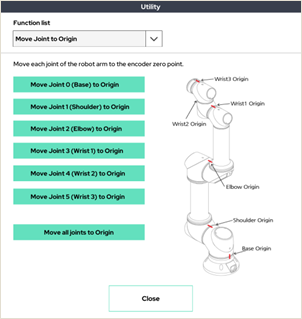
Move each joint to the mechanical origin marked on the robot arm.
3. Free-Drive with Constrained Orientation
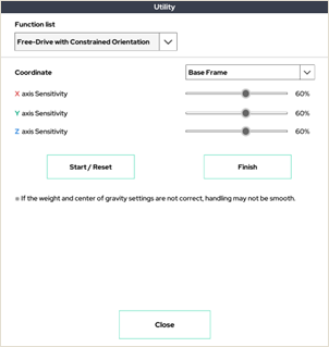
This mode is only available in Real Robot mode.
Axes with low sensitivity settings are not actuated in direct teaching mode, and only axes with high sensitivity settings are actuated.
4. Input Signal View
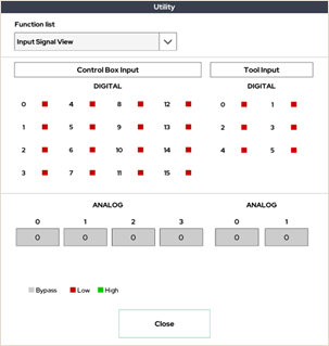
Input signal monitoring window for control box and tool flange.
5. Output Signal View
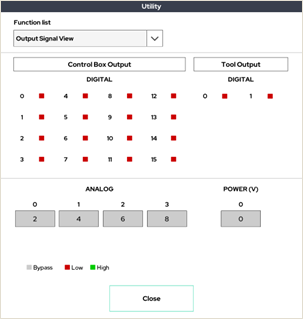
Output signal monitoring window for control box and tool flange.
6. Status
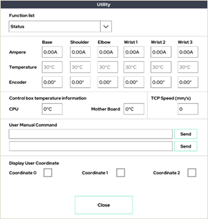
This window allows the user to see the robot arm’s current and temperature. It also shows the user coordinate system settings.
7. Snap
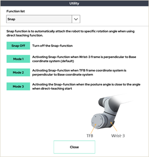
Snap mode selection window to be applied when using direct teaching mode.
8. Box Output Test
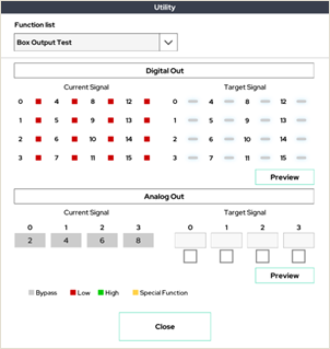
This window allows you to test the output of the control box.
9. Tool Output Test
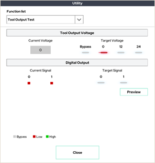
This window allows you to test the output of the tool flange.
10. I/O Extension Board
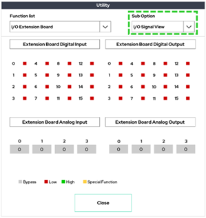
I/O expansion module's I/O signal monitoring window.
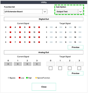
Window for testing the output of the I/O expansion module.
Setting sub functions
1. Tool List Select
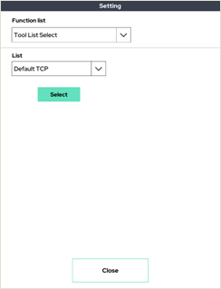
There is a Tool List Select setup feature that sets up TCP to use in a pre-saved TCP list. A total of four tool lists can be set.
2. Joystick
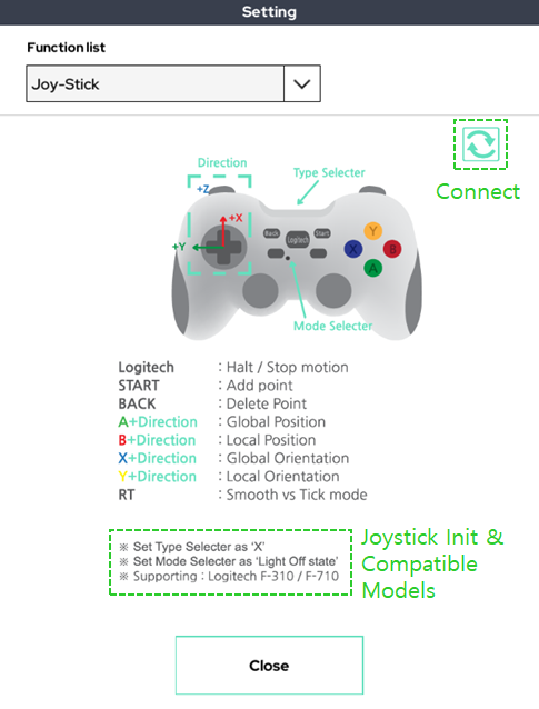
When teaching a robot using a wired/wireless joystick, there is a joystick connection setting function.
The joystick has the compatible model listed below and must be initialized.
When all settings are complete, click the button on the refresh mark at the top right to connect.
3. User Coordinate
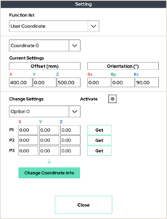
Set the user-defined coordinate system. Press the activation button to display a screen that selects three points.
This is the 3-point setup mode (see 7.7 Setup-Coordinate).
4. User Coordinate Center
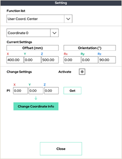
Keep the XYZ axis and rotation direction of the previously set user coordinate system, and move only the origin.
5. Auto TCP
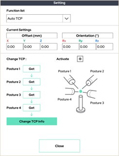
It automatically finds the position of the robot end (TCP).
If you enter four different postures that keep the TCP point you want to set at the same point in a three-dimensional space, it automatically calculates the TCP position value.
Take each position as shown, and press 'Get' on the corresponding number.
6. High Precision Auto TCP
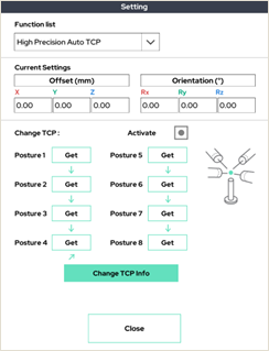
It automatically finds the position of the terminal, just like the robot terminal (TCP). However, it has more posture, so it looks for more precise TCP.
7. External F/T
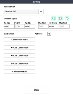
This window allows you to check and calibrate the external F/T sensor (e.g. Robotiq F/T sensor).
8. Auto COG/Mass
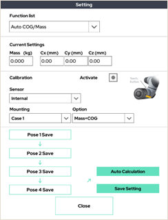
This function finds the weight and center of gravity attached to the tool using the internal / external F/T sensor.
9. Motion Recording
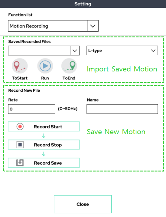
It is a function that records the motion through the direct-teaching(gravity compensation) function. The recorded action is available in the program via the Replay function.
10. I/O Logging
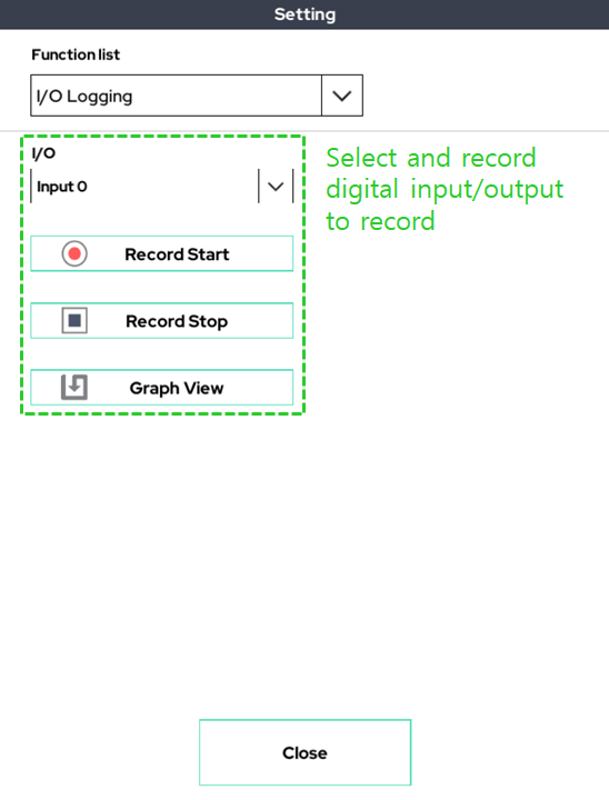
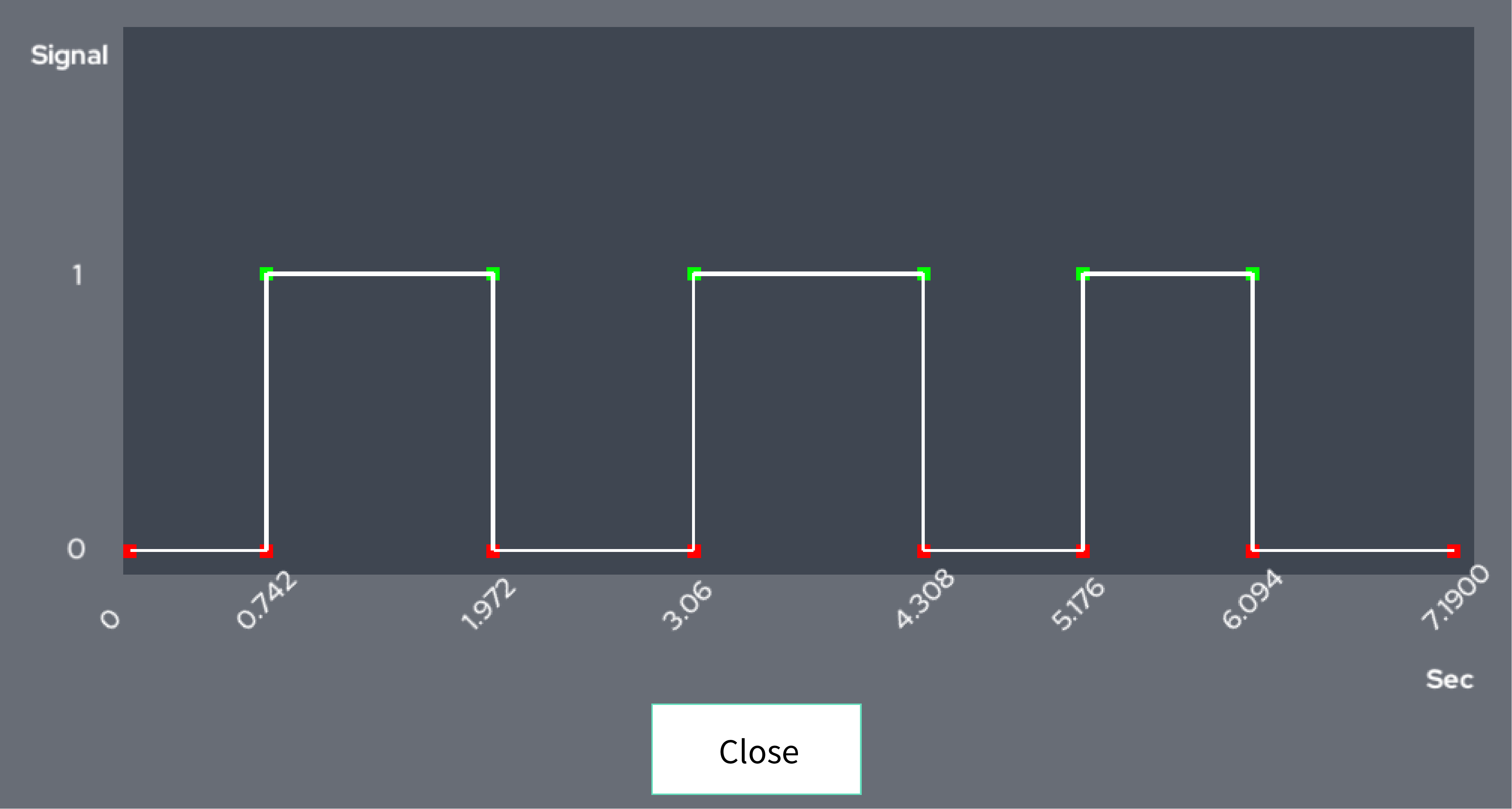
This function sets one digital input/output, records the change in the value of that input/output, and shows it graphically.
11. Welder Wire Control
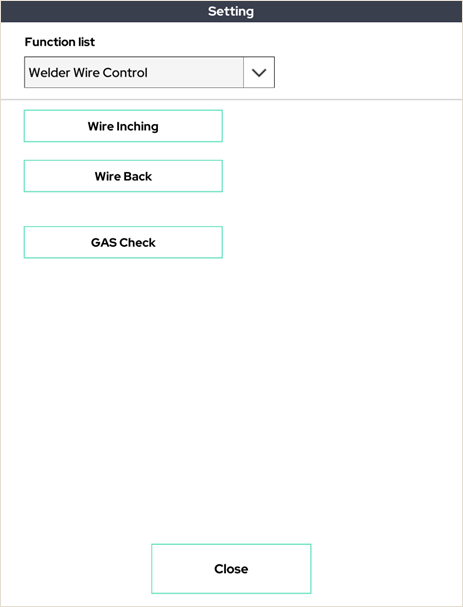
This function can control the welding machine's wire.
12. TCP Orientation Change (Frame)
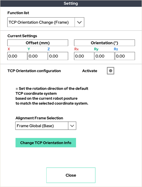
Sets the rotation direction of the default TCP coordinate system based on the current robot pose to match the selected coordinate system.
13. User Coordinate Auto Alignment
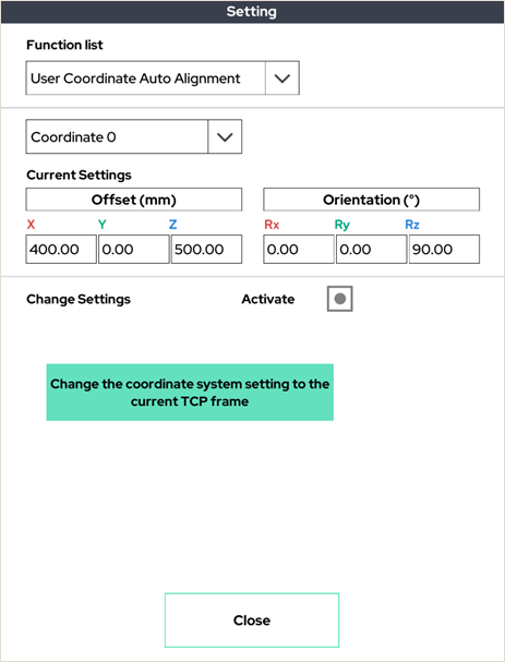
Change the coordinate system setting to the current TCP frame.
14. External Axis Calibration
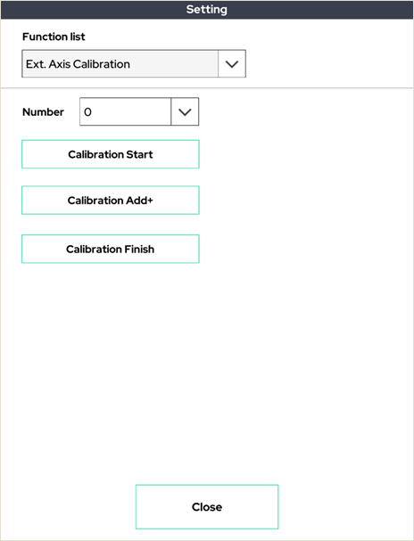
This is a process to inform the robot arm of the external axis of rotation and the radius of rotation.
This calibration allows the robot to control the synchronization of the external axis.
15. Safety Plane
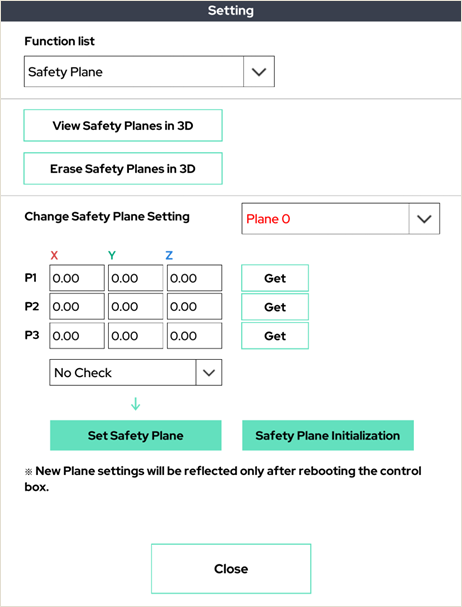
Set the plane that the robot arm cannot cross for safety. If it crosses the set plane, the robot arm will stop.
16. Safety Joint Range
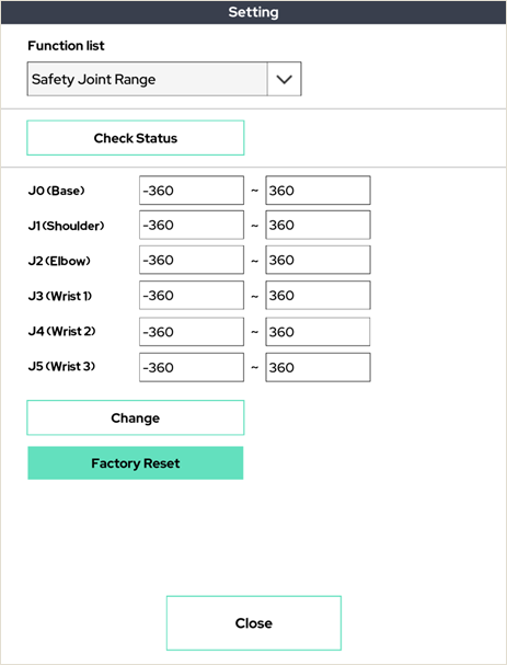
You can specify the range of angles that operate for each joint in the robot arm. An angle greater than or equal to the specified joint angle value will not operate.
17. Global Pin Point
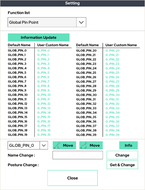
This is the function to set up global pin points. As shown in the above picture, you can set up global pin points to share the variables in multiple programs.
18. Orientation Aligning
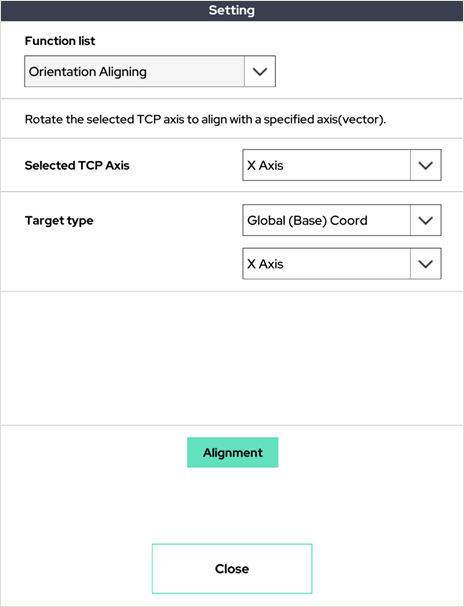
Rotates the axis of the selected TCP of the robot arm to align with the specific axis.
19. Check Lastest System Log
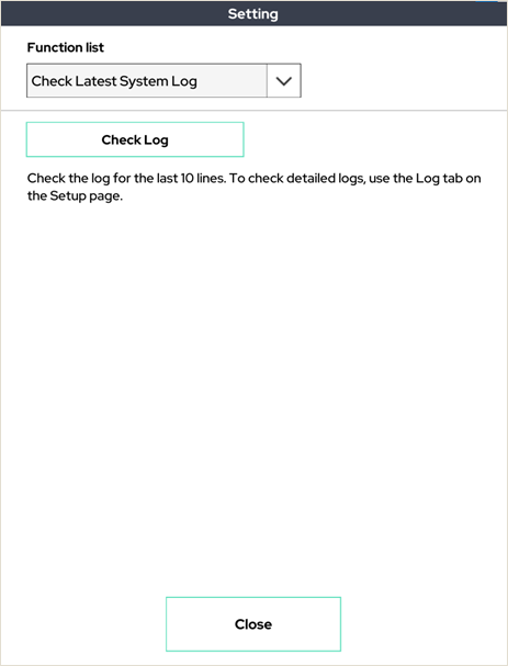
Displays the contents of 10 lines of the latest log file on the system on the UI.
20. Joint Origin Field Calibration
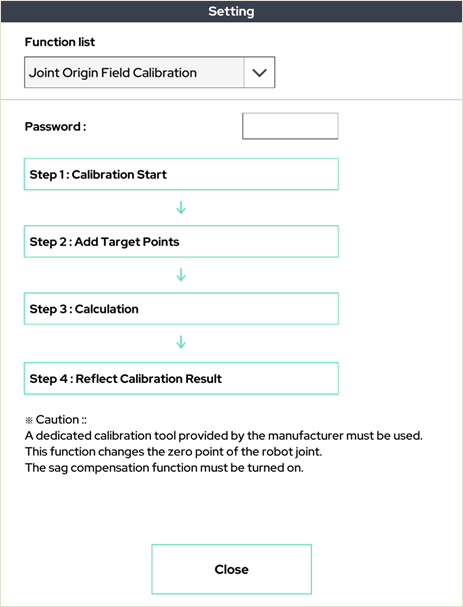
This function is to calibrate the joint 0 points on the spot. Please contact the manufacturer for more information.
Monitor Function
This function is used in conjunction with the Monitor command in Section 6. This window allows the user to observe the system and user variables in real time.
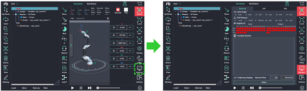
By pressing the recording function on the upper right, the TCP trace of the robot tool is recorded in the 3D viewer in the 3D viewer. (Yellow solid line)
The recording time is up to 30 seconds.
3D View Function
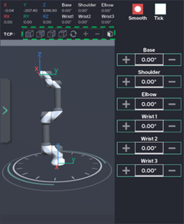
It has a three-dimensional viewing angle that is frequently used. It can be used if you want to quickly change the view of the three-dimensional viewer.